This thread has been locked.

If you have a related question, please click the "Ask a related question" button in the top right corner. The newly created question will be automatically linked to this question.

TPS23755: Use of general-purpose transformers

Part Number: TPS23755
Other Parts Discussed in Thread: , TPS23753A

Hello,

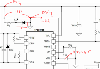
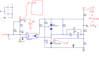
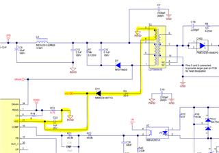
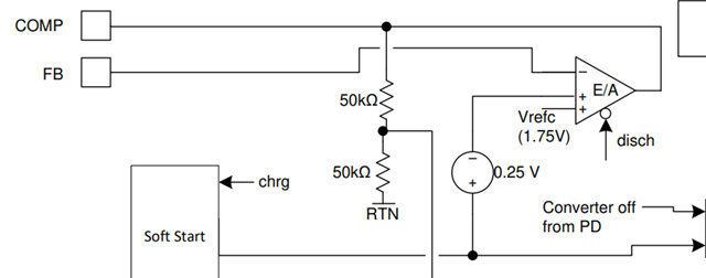
Is it possible to configure a circuit using a general purpose transformer without feedback windings?
(e.g. optocouplers, isolated amplifiers, etc.)

If that configuration is possible, please provide a reference circuit.

Regards,

  • Hi Sir/Madam,

    Thanks for reaching out to us!

    TPS23755 has integrated current-mode DC-DC controller and normally it is for closed-loop control. Theoretically, it could be configured to open-loop voltage-mode control by adding a PMW generator but it is rarely used since the regulated voltage will be vary with different input voltages or load currents.

    Another way to get rid of the optocouplers or isolated amplifiers circuit is using flyback circuit with primary side regulation. It will sense the auxiliary winding voltage to get the Vout information when it has a ratio to Vout (as the picture shown below, but TPS23755 does not have ). It needs PRI, SEC, and AUX windings like the convectional PoE transformer. 

    TPS23755EVM-894 (ti.com/lit/ug/slvubg8a/slvubg8a.pdf) is with the primary side regulation. The optocoupler in the schematic is for Vout hitless transition when switching from adapter to PoE. If you do not have adapter, you do not need this part. 

    Please let me know if you prefer open-loop or primary side regulation.

    Best regards,

    Diang

  • Hello, 

    My explanation was insufficient.
    I meant that I do not want to get rid of the optocoupler or the isolated amplifier, but rather use a transformer without auxiliary windings even with them.
    Of course, if it is possible to achieve that without optocouplers or isolated amplifiers, that would be best.
    If so, what circuit configuration is possible?

    Regards, 

  • Supplemental

    Transformers with auxiliary windings: I don't want to use them
    Optocouplers: may be used

  • Hi Sir/Madam,

    The auxiliary winding for PoE application is mainly for supporting Vcc after startup. Vcc is the primary side gate drive positive rail voltage. 

    If you want to make a design without the auxiliary winding, instead, you need to add a voltage regulator with 37-57 V input and ~13 V output voltage at the primary side. Connect the output of the voltage regulator to Vcc-RTN and set a suitable timing for it.

    Best regards,

    Diang

  • Hello, 

    Are you saying that the role of the auxiliary winding is not to provide feedback but to supply Vcc?
    If so, is the auxiliary winding unnecessary if Vcc is supplied by the connection shown in Figure 8-2 in the datasheet, without using a voltage regulator IC? (Is an optocoupler also unnecessary?)

    Regards, 

  • Hi Sir/Madam,

    The main purpose of auxiliary winding is for Vcc and not for supporting feedback. Only in primary side regulation, it is also used for feedback control. 

    In Figure 8.2, the auxiliary winding is actually used to support Vcc. Optocoupler could be unnecessary here if you use primary side regulation.

    Best regards,

    Diang

  • Hello, 

    It is Figure 8-2, not Section 8.2.
    In the flyback circuit, can the following connection be used to supply power to Vcc?

    Regards, 

  • Hi Sir/Madam,

    Sorry that I mistook Section 8.2.

    In Figure 8-2, it used a linear regulator here to get Vcc voltage close to the Zener diode voltage. It has simply schematic but relative low efficiency. Assuming you have 15 V at Vcc and 0.15 W power on it (0.01 A current in series), this circuit may take over all 0.5 W assuming you have 50-V input voltage. 

    You can use this circuit if the power loss is not the major concern for you. Meanwhile, please consider to add some capacitors to allow a > 80 ms delay time for ensuring the PD's inrush period is passed when DC/DC switching starts. 

    Best regards,

    Diang

  • Hello, 

    I understand about the supply to Vcc. Thank you very much.
    Then please tell me the circuit configuration of the flyback section.
    I do not know how to control the voltage on the secondary side (e.g. how to connect FB, CP, etc.).
    There is no reference circuit diagram for the flyback configuration using a general-purpose transformer in the datasheet, can you provide one?

    Regards, 

  • Hi Sir/Madam,

    In general we need to disable the internal error amplifier of the PD to enable optocoupler based feed back control. A circuit is shown below.

    Some of PD's error amplifier could be disabled by tie the FB to VB. But I did not find this description on TPS23755/8's datasheet. 

    To avoid the risk, I would recommend you to use other AT PDs that do not support PSR. For example, you can use PMP8896 (https://www.ti.com/tool/PMP8896) which is based on TPS23753A. 

    Best regards,

    Diang

  • Hello,

    I don't understand your answer.
    So your answer "The main purpose of auxiliary winding is for Vcc and not for supporting feedback." was wrong?

    I am not considering using TPS23753A.
    I would like you to answer the circuit configuration using TPS23755, are you saying that there is no other feedback method other than using the auxiliary winding?

    Regards,

  • Hi Sir/Madam,

    It is correct that "The main purpose of auxiliary winding is for Vcc and not for supporting feedback. Only in primary side regulation, it is also used for feedback control. " If you use the optocoupler based secondary side regulation, you do not need the auxiliary winding in the feedback loop.

    Please find attached two reference designs for TPS23755 with secondary side regulation. You can use the linear regulator to replace the high-lighted auxiliary winding loop. Let me know if you have any further questions.

    PMP22050B(001)_Sch.PDFPMP21993B(001)_Sch.PDF

    Best regards,

    Diang

  • Hello,

    If the FB pin cannot be disabled, does that mean feedback is always required?

    If so, please let me know if there is a way other than using an auxiliary winding or optocoupler.

    Regards,

  • Hi Sir/Madam,

    Inside the FB is the internal error amplifier of the TPS23755. And yes, FB is used for feedback control. To enable the feedback control, you will need either auxiliary winding or optocoupler generally. 

    Please let me know if you only need an open-loop control. If so, you do not need auxiliary winding or optocoupler.

    Best regards,

    Diang

  • Hi Sir/Madam,

    Since we have not received your response for a relative long time, I will close this thread for now.

    The reply on Jan/19/2023 was recommended as the solution: secondary side regulation with optocoupler +  linear regulator to replace the highlighted auxiliary winding circuit.

    If you have any further questions please reply or open a new thread.

    Best regards,

    Diang