This thread has been locked.

If you have a related question, please click the "Ask a related question" button in the top right corner. The newly created question will be automatically linked to this question.

BQ25886: BQ25886 STAT PIN BLINKING

Part Number: BQ25886

Hi,

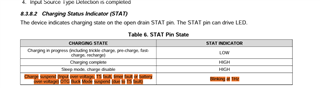
In this design, while testing, The PG LED is turned ON. However, the STAT LED is blinking at 1 HZ. While looking in the datasheet, multiple reasons are listed for this behaviour.

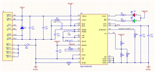
The input Voltage is 5.12 V. Battery Voltage is 7.23 V.

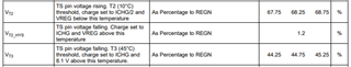
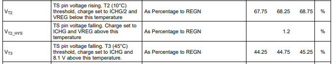
Here I am not using NTC and the voltage across the TS pin is around 4.1 V. Is not using an NTC an issue? What combination should I use for the voltage divider ignoring the NTC? or is there any other issue?

Note: R5 = 5.23 K, R8 is 30.1K. R7 is not populated.

  • Hi Syed,

    If an NTC thermistor is not used, the TS pin needs a voltage between the percentages below relative to REGN.  So set R5=R8.

    Regards,

    Jeff

  • Hi,

    I have added the resistor accordingly and now, the voltage across the TS pin is 2.29V and the STAT LED is constantly ON now.

    However, the charging voltage is just 8.01V instead of 8.4V. What could be the possible reasons for drop-in charging voltage?

    Note: RSET = 150 K (R2)

  • Hi Syed,

    Is the charge voltage = 8.01V being measured at the IC BAT pin?  Has the charge current started tapering down from the maximum?  How resistive is the connection from the BAT pin to the battery pack?

    Regards,

    Jeff

  • Hi,

    I found that it was due to the resistor on TS pin due to which the third condition is triggered. 

    However, I am suddenly having a new issue. The device was working fine. And one day later, when the USBC is plugged in with the battery connected (V BAT = 7.86 V), the PG LED toggles and turned off. However, when I try to plugin without a battery, the PG LED is ON and STAT LED is blinking. As soon as i connect the battery, the PG LED toggles and turns OFF.

    VUSB = 5.12 V

    REGN = 5.08V

  • Hello,

    What is physically different between when it is working and when it is not?

    Please share waveforms of VBUS, SW, VBAT, and ICHG in both cases.

    Is your input capable of providing enough current (See Section 8.3.8.1)?

    Regards,

    Mike Emanuel

  • Hi,

    Found that this is again due to the resistor across TS pin. When I changed the R5 to 5.1K and R8 to 30K, the cut-off issue was solved. However, the STAT LED is keep on blinking (again due to TS Voltage) which is around 4.3 V.

    However when I use R5 = 5.1K, R8 to 30K and R7 (instead of NTC) to 4.7K, the issue is resolved. But the charging voltage is only 8.14V without battery and 8V with a battery. VREGN = 2.2V

    This may be a stupid question (I am a newbie here) but according to the below table:

    The voltage across TS should be around 1.2% of VREGN (5.08 V) which is around 0.061 V. Am I correct? However, if R5 = R8, then the TS  voltage is around VREGN/2 (2.54 V) which is around 50% of VREGN. Dos this create any issues here?

  • Hello,

    The TS voltage needs to be between VT2 and VT3 for full charge and charge current. Otherwise the restrictions shown in Figure 19 apply. The 1.2% you are referring to is hysteresis, not full value.

    Regards,

    Mike Emanuel

  • Hi,

    Thanks. Now i have modified the resistor combination in such a way that the voltage across TS pin is 2.51V (49.4% of VREGN). But I noticed a different behaviour.

    When I connect the USB cable without Battery, the STAT LED blinks at 1 Hz. But if i plug in when the battery is connected, the PG LED blinks 5-6 times and turns off.

    I also have a few doubts, I have set the charging current to 2A (R-ICHRGSET 7.87K) and D+ and D- are shorted through a 100E resistor. And the input current limit resistor is 383 Ohms. Does this create any issues with charging?

  • Hi,

    I have changed the R-ICHRGSET to 1K. Now the PG led works fine and STAT is also not blinking and is continuously ON. However, the voltage across the BATT pin when the battery is not connected is 8.5 V and when it is connected, it is 8 V and gradually increases in steps of 0.01 V for every 5 min and reaches 8.35 V within 40-45 min.

  • Hello,

    I have several questions related to the numbered posts:

    1. In the first post, what was the input voltage supplied when the PG LED blinks 5-6 times? Were you capable of providing V_POORSRC when pulling I_POORSRC as shown in Section 8.3.3.1? Those settings should not cause any issues

    2. With RICHGSET at 1k the charge current is 262 mA. I suspect the long charge time is due to the limited charge current.

    Have you verified your input is capable of supplying 3.3 A at 5 V?

    Regards,

    Mike Emanuel

  • Hi,

    1. The input voltage was 5.12 V (Through a Samsung charger). However, when the battery is connected, the voltage is fluctuating between 2.1 to 3.8 V. 

    2. I noticed that the input capacity of the adapter can deliver only 2A @5V. Here I changed only the R-ICHRGSET resistor without modifying any other components.

    Here is my question:

    is ICHRGSET the maximum current capacity or do we definitely need to provide maximum current to initiate the charge? Eg: if we set the ICHRGSET to 2A and if we use a 1A charger, will the IC automatically reduce the charging current or it won't start charging?

    And while charging with RICHGSET at 1k, the battery voltage is charging beyond 8.56 V instead of 8.4V and not cutting off.

  • Hello,

    If the input voltage is fluctuating between 2.1 V to 3.8 V when the battery is plugged in but 5.12 V unloaded, the device is failing poor source at 3.7 V and is out of the minimum operating range minimum of 4.3 V. Please ensure the adapter provided is capable of sourcing the total power needed for your system. 

    Please see Section 8.3.6.2 Dynamic Power Management about what happens when the input is overloaded. However, I think your case is on the extreme of this behavior because the device cannot even regulate the input at VINDPM.

    Regards,

    Mike Emanuel

  • Hi,

    The input voltage fluctuation is solved as soon as the RICHGSETis changed to 1K from 7.87K.

    And now the battery is charging. But the issue now is the battery voltage is charging beyond 8.56 V instead of 8.4V and not cutting off. (Even with RVSET 150K and floating)

  • Hello,

    The RICHGSET resistor keeps changing. What is the desired charging current? Are you positive the adapter can handle the required current?

    Can you measure the resistance from VSET to GND?

    What happens if you try another device?

    Regards,

    Mike Emanuel

  • I manually changed the RICHGSET  value to 1K from 7.87 K. The adapter is capable of delivering up to 1.5 A. Also, what happens if I use a 1A adapter on a 2A ICHGSET? Will this IC automatically downgrade the charging current? 

    The resistance was initially 150K between VSET to GND. Also, now the VSET pin is floating still facing same issue on charging voltage

  • Just to clarify, with a 1k RICHGSET the charging current will be 262 mA, not 2 A. 

    As shown in Section 8.3.6.2 Dynamic Power Management with regards to the input current, "If this current exceeds the charger's preset input current limit or causes the input source voltage to droop near the input voltage limit (VINDPM fixed at 4.3 V typical), the device then reduces the charge current until the input current is regulated to the input current limit or the input voltage is regulated to the VINDPM threshold."

    Can you try changing the IC and seeing the result? Floating VSET corresponds to 8.4 V charge voltage.

    Regards,

    Mike Emanuel

  • Hi,

    Even with different charging IC, the charging voltage is still 8.54 V (VSET Pin is floating)

  • Hello,

    How are you measuring this charging voltage?

    Regards

    Mike Emanuel

  • Yes. Voltage across VBat pin on IC and GND. Tested on 2 Boards. Same result. Battery voltage is 7.96 V. But while charging the bat pin voltage is 8.54V

  • Hello,

    I am confused by your measurement. The battery is a steady DC source. If you attached 7.96 V battery, the battery voltage will not suddenly jump by 500 mV. How is you ground connection situated? Have you tried another IC on another board?

    Regards,

    Mike Emanuel

  • Hi,

    no what i am saying is that i started to charge the battery at 7.96. But even after reaching 8.5, the charging didn’t cut off. When i measured the batt pin voltage while charging without battery the voltage is 8.54V. 

    I have tried with 2 diff boards. Same result 

  • Hi,

    During this state, can you measure the impedance VSET sees to GND?

    Regards,

    Mike Emanuel

  • Hi,

    When the battery has not connected the resistance between the VSet PIN and GND is in terms of 0.5 MOhm.

    However, as soon as the battery is connected, the resistance between VSET and GND is 8 KOhm. Is it normal? 

  • On my board when I have open VSET pin it is open with no power applied. When I apply power it goes to about 10kOhm (I am less concerned about the measurement when the IC is on). What happens when you terminate it with 150k?

    Can you please capture a waveform when the measured battery voltage is above the desired charge voltage regulation with VBUS, BAT, SW, and the charge current? Place a cursor on the BAT pin voltage showing it is above the 8.4 V regulation. Please capture the same waveform measuring VBUS and please reconcile it with the multimeter measurements for both.

    Regards,

    Mike Emanuel

  • Hi,

    Sorry, I don't have an oscilloscope with me. I will try to get it done.

    However, we assembled a 3rd board and tested it. Here the VBAT voltage while charging is 8.42V. (VSET pin floating)

    Also, the battery charging got terminated as soon as the battery reached 4.23V.

    The previous 2 boards, it has undergone multiple resoldering. Does that have any effects on battery charging voltage?

  • Hello,

    I am confused by your results. Did the battery terminate at 8.42 V? Terminating at 4.23 V is well below the charge regulation. Did you mean the individual cell (of which there are 2) terminated at 4.23 V?

    The best way to know is to perform an ABA swap. Take a known good and put it on the bad board, take the known bad IC and put it on the good board. Observe the results.

    I await your scope captures.

    Regards,

    Mike Emanuel