This thread has been locked.

If you have a related question, please click the "Ask a related question" button in the top right corner. The newly created question will be automatically linked to this question.

TPS65987D: TPS65987D + TPS55288 Schematic review

Part Number: TPS65987D
Other Parts Discussed in Thread: TPS55288, TPS65987

Hi,

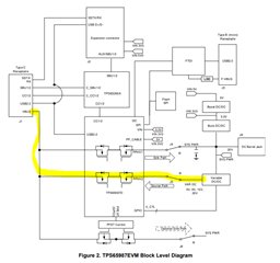
Customer is review the Type-C charging port on the portable ESS.

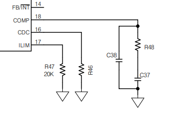
There is an application note for TPS65987D + TPS55288 as shown in the link below.

USB Type C Power Delivery Source with TPS65987 and TPS55288 (ti.com)

Please review the schematic of TPS65987D + TPS55288.

Schematic.2pdf.pdf

  • Hi Cho,

    Please give us a week to review the PD portion of the schematic.

    Thanks and Regards,

    Chris

  • Hi Cho,

    What is the use case for this design?

    • What kind of product is being made
      • Is this port supplying power, charging, providing/taking data?
    • Are you looking to source power/sink power, both?
    • Any data requirements
    • How much power is desired for source/sink?

    Please go through the attached spreadsheet. Red items need to be fixed, Yellow are recommended, and Green are good.

    Comments:

    It seems like the flow of power in this design is off. When designing the power path for a Source device, power should come from the output of a power supply, go into the PPHV(1 or 2 depending on design) pass through the internal power path, exit the TPS65987 from the VBUS pin(1 or 2 depending on design), and exit through the VBUS pin of the Type-C connector. In the shared design, the output of the power supply is connected directly to the Type-C connector.

    The image below is from the 987EVM user manual, and is not an exact representation of your system. I added it to highlight the power path connections.

    Additional Comments/questions

    • If this is a source application, you may need to change the capacitors on PP_HV(see lines 8-11 of spreadsheet)
    • Did you choose the FTDI MCU from the 987EVM?
      • We do no support the design around that part. We recommend either following the EVM schematic exactly or reaching out to FTDI.
    • There are many GPIOs that have unattached nets.
      • Is this intentional (i.e. separate sheet?)
    • If you are a source, you will need a separate 5V source for the PP1_cable pin. Please refer to 8.3.1 in the datasheet for why it is required.

    Thanks and Regards,

    Chris

  • Hi Cho,

    Thanks for reaching out on E2E.

    Please reply with the application conditions like input voltage range, output voltage range and max output current. And I don't see any value on ILIM, CDC and COMP pins, is there any thing missing from the schematic?

    Regards,

    Bryce

  • Hi,

    Sorry for the late reply.

    The customer is delaying the feedback on the question. 

    I will ask you a question with a new case after the case is closed.

  • Hi Cho,

    Thanks for reply, I will close this thread. You can ask a new question when you get feedback.

    Regards,

    Bryce