This thread has been locked.

If you have a related question, please click the "Ask a related question" button in the top right corner. The newly created question will be automatically linked to this question.

TPS62056: Problem with forced-fixed frequency PWM mode

Part Number: TPS62056

Hello, I have a design in production I am seeing problems with, input voltage is 5.0V and output voltage is 3.3V.

Trying to operate in low noise mode, by holding the sync input to high to force fixed frequency PWM mode. Most devices operate at a fixed frequency of approx 800-900kHz.

Some devices operate at a much lower 80-90kHz which makes me think they are operating in the power-saving pulse frequency modulation (PFM).

Spraying the device with a small amount freeze spray will cause it to move to the 800-900kHz range.

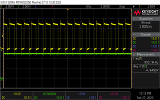
I have attached scope screen shots of the SW pin on channel one, and the SYNC input on channel two.

This first one shows the typical faulty mode of operation:

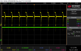
This second one shows the device working as expected:

The problem is, when the converter operates in the 80-90kHz mode, the product doesn't work due to excessive noise on the 3.3V rail. 

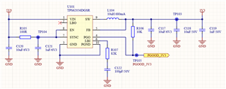
Here is the schematic, I know there is a resistor and capacitor on the LBI input that doesn't make sense, but this should not cause any problems.

I have replaced the failing designs with known sourced ICs from Mouser, but they can still show the same problem after replacement.

  • Hi Ian,

    It is abnormal. Here is my suggestion.

    1. Please measure SYNC pin voltage on a failure part to make sure it is high and not low. What is the voltage level difference before/after cold spray?

    2. Try to remove C121, R107 and C122 which are not needed. This will rule out the possible issue from those parts. Especially C121 decoupling cap on sync pin.

    3. Deep clean TPS62056 area with alcohol or ultrasound cleaner to make sure no flux contamination. 

    4.  If above 4 items are not working, please send me the PCB layout file. I will review it.

    Thanks,

    Nancy

  • Thanks Nancy,

    1) The voltage on the SYNC pin is shown on channel 2 of the scope trace, it is always 5V.

    2) I have removed C121, R107 and C122 - no change to the switching frequency.

    3) I have ultrasonically cleaned a board - it made no difference.

    4) I will attached the PCB file shortly.

  • Hi Ian,

    The PCB layout is very poor and may cause abnormal operation. Please see my schematic and layout comments as attached.

    TPS62056 Schematic_layout review.pptx

    Thanks,

    Nancy