This thread has been locked.

If you have a related question, please click the "Ask a related question" button in the top right corner. The newly created question will be automatically linked to this question.

LM27761: What is wrong with my circuit?

Part Number: LM27761

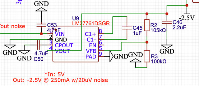
Hi guys, image of circuit attached. 

C50,53 = 4.7uF 

C55 = 1uF

R2 = 105K

R3 = 100K

C46 = 2.2uF

As per equation 5; -1.22 * (105K + 100K)/100K = -2.5

Why wont this circuit output anything? I have tried 3 different chips all new. I can only think that using resistor values as high as 100 and 105k are the problem but regardless i didnt think that should be the issue as R2 should not be below 50K either as stated by datasheet. Power goes in, i can see 5V is input but the output is not working. 

Is it perhaps because i have left the EN floating? Couldnt find mention of leaving it floating in the datasheet? 

Thanks for any help :) 

  • Hello Rishan, 

    Thank you for reaching out. 

    The EN pin is available to disable and enable the device. In page 10 of datasheet, it is stated that a voltage greater than 1.2V needs to be applied to the EN pin to bring the device into enable mode. So leaving the pin floating will keep the device disabled. 

    You can connect the EN pin directly to VIN, so the device powers up when an input voltage is applied. 

    Best regards, 

    Natalia

  • Amazing ok so i set up the enable, and my device works through some very sketchy soldering haha. But my voltage is around -2.8 now. Would you be able to help explain where the difference is coming from? As i explained before, my R1 and R2 values seem to be correct. 

    Thank you for the help!!!  

  • Hi Rishan, 

    You can start by checking the VFB voltage, which should be in the range of 1.202V - 1.22V - 1.238V.

    If that is correct, I would suspect on the voltage divider.

    Best regards, 

    Natalia Usuga

  • Hi Rishan, 

    I will close this thread. Please feel free to re-open it by commenting to this post. 

    Regards, 

    Natalia