This thread has been locked.

If you have a related question, please click the "Ask a related question" button in the top right corner. The newly created question will be automatically linked to this question.

UCC14240-Q1: Overpower protection clarification

Part Number: UCC14240-Q1

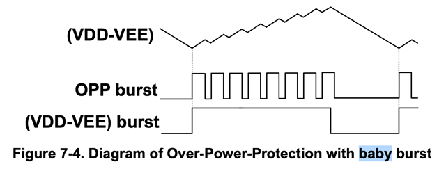
I'm confused by Figure 7-4 in the UCC14240-Q1 data sheet. If the OPP function is active, then surely that means the load is trying to draw more power than the device can deliver? In which case, wouldn't the VDD-VEE voltage decrease until the power consumed by the load equals the maximum output power of the device or the output undervoltage protection kicks in?

Figure 7-4 appears to show the VDD-VEE output voltage rising until it reaches the upper threshold of the hysteretic control scheme, whereupon the control loop turns off the primary-side inverter. I don't understand how that's possible while the OPP is active.

Or have I misunderstood the OPP function? Does it simply compensate for higher input voltages and always generates the baby burst, even when the load is not trying to exceed the maximum output power? Is that what Figure 7-4 is trying to show? 

Any clarification would be welcome.

Regards,

Nigel

  • Nigel,

    The effect of OPP is shown on the voltage regulation curves (shown below from the UCC14240EVM-052 User Guide) seen as a sharp knee where the voltage drops as load current is increased. Input voltage feedforward results in the max power level where the "knee" is observed increasing as input voltage is increased. As the output voltage drops because of overload, the Under Voltage Protection (UVP) will trigger a FAULT when VDD-VEE is < 90% of set-point, resulting in shutdown. The FAULT can be reset by toggling ENA pin or VIN voltage below and over UVLO. Because the converter is operating using hysteretic control at a very high switching frequency, it is not practical to implement traditional cycle-by-cycle current limit in the way you've described.

    Regards,

    Steve M

  • Steve,

    You haven't really addressed my questions, which pertain mainly to the meaning of Figure 7–4 in the data sheet. Could you please re-read my original post?

    Furthermore, your answer has confused me even more. You say that the voltage feedforward in the OPP is the reason why the knee of the curve in the your figure moves to the right as input voltage increases, yet the following sentence from the data sheet implies that it should maintain the maximum output power more or less constant, regardless of the input voltage.

    When the input voltage increases, the DOPP reduces automatically to limit the averaged output power.

    Maybe I'm being a bit slow, but it's not at all clear from the data sheet how the OPP actually works.

    Regards,

    Nigel

  • Nigel,

    Is the explanation of OPP not clear? Did you have other questions about the function? Let me go back and try to address each of your questions individually as below:

    If the OPP function is active, then surely that means the load is trying to draw more power than the device can deliver?

    • Correct, OPP burst is always active and as the load tries to draw more power than the device can deliver, output voltage drops until output UVLO is reached.

    Wouldn't the VDD-VEE voltage decrease until the power consumed by the load equals the maximum output power of the device or the output undervoltage protection kicks in?

    • Correct

    Figure 7-4 appears to show the VDD-VEE output voltage rising until it reaches the upper threshold of the hysteretic control scheme, whereupon the control loop turns off the primary-side inverter. I don't understand how that's possible while the OPP is active.

    • I think Figure 7-4 would be more clear if you think of OPP burst as baby burst. Fig 7-4 assumes the converter is in regulation, the converter is not in OPP (operating over the knee region I showed previously) and the converter is operating within the hysteretic band as you correctly understand.

    Or have I misunderstood the OPP function? Does it simply compensate for higher input voltages and always generates the baby burst, even when the load is not trying to exceed the maximum output power? Is that what Figure 7-4 is trying to show? 

    • Correct, the baby burst is always present but the Mama burst duty cycle is modulated according to the demand of output power needed up to the max power that can be delivered according to input voltage and/or max operating temperature

    Steve

  • Thanks Steve,

    That's much clearer now. 

    Regards,

    Nigel

  • Nigel,

    Thanks for connecting through E2E!

    Steve