Hi team
this is my customer SCH could you help me to review it ?
because I will LOA next week
can you reply this week?
there are six TPS25985 in attached files
BRs
brian
This thread has been locked.
If you have a related question, please click the "Ask a related question" button in the top right corner. The newly created question will be automatically linked to this question.
Hi team
this is my customer SCH could you help me to review it ?
because I will LOA next week
can you reply this week?
there are six TPS25985 in attached files
BRs
brian
Hi Brian,
Thanks for reaching out. I will get back to you by tomorrow.
Hi Brian,
Please see the observations below.
1) SMDJ12A or equivalent TVS diode needs to be added at the input of every TPS25985 schematic.
2) PMEG045V100EPE-QZ or SBR10U45SP5-13 or equivalent Schottky diode needs to be added at the output of every TPS25985 schematic.
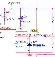
3) MMBZ5230B should be used in all the schematics instead of MMBZ5226B. This resistor (highlighted with yellow color) should be 10k, not 100k.

4) As there is already a 3.3V standby power supply rail, which is being used for PG pullup, same can be used for FLT_N pin. May I know any specific reason for using resistor divider from VIN?
5) Ceramic capacitor connected to the IREF pin should be 1 nF instead of 150 pF. This is applicable for all the schematics.
Please click on "This resolved my issue" if this post answers your query.