This thread has been locked.

If you have a related question, please click the "Ask a related question" button in the top right corner. The newly created question will be automatically linked to this question.

PTD08D210W: The output current on the system monitor is not correct on FUSION DIGITAL POWER DESIGNER

Part Number: PTD08D210W
Other Parts Discussed in Thread: UCD9248, , UCD9224EVM-464

Hello,

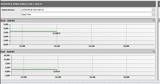
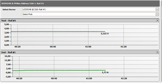
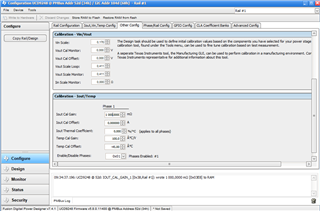
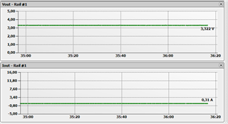
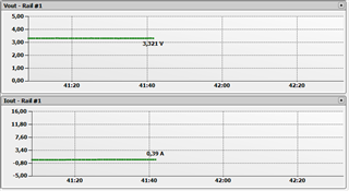
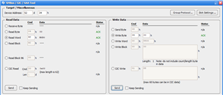
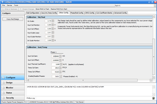
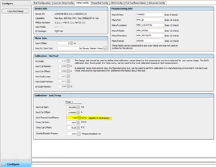
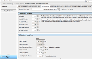
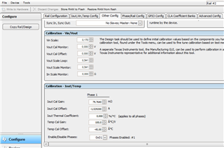
I use the software FUSION DIGITAL POWER DESINGER and I got a problem in the monitoring window, the output current is not corresponding to the real current.

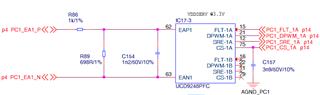
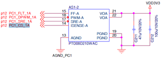
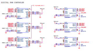
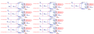
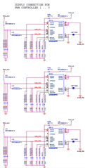
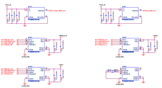
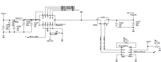
I have a UCD9248 and a PTD08D210 components on the board.

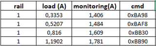
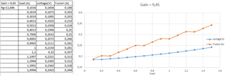
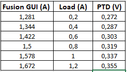
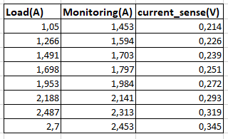
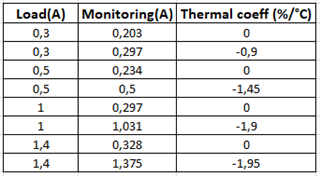
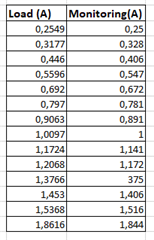
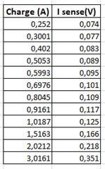
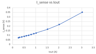
I put a variable load at the output and an ampere meter to see in real time the value of the current.

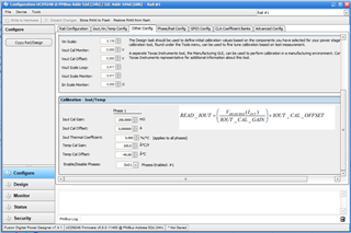
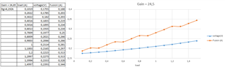
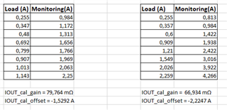
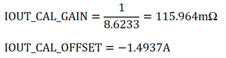
If I modify the values of the Iout cal gain and Iout cal offset, this change the value of the current on the monitoring.

Even if I modify this two parameters to have the same current on the amperemeter and the monitoring, this is valid only for this current because if I modify the charge value, the current on the amperemeter and the monitoring are differents.

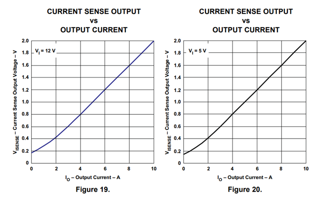
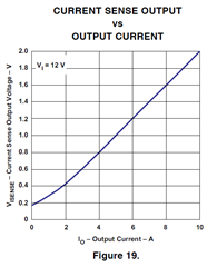
The evolution of the current on the amperemeter is in correlation of the current in the datasheet of the ptd08d210W page8 figure19.

Is-there a parameter or a specific configuration to have to observe the current in real time on the system monitor?

If you want some specification or screenshot don't hesitate.

Thanks in advance,

Maxime

  • Hi Maxime,

    Please verify with a voltmeter if the current sense outputs (Pin #6 and #14):

    Respond according to the following curves:

    If these output act accordingly, then the PTD08D210W module is functional.
    In that case, I will redirect this to the group that supports UCD9248, so they can assist you further.

    Regards,

    Yitzhak Bolurian

  • Hi Yitzhak,

    Thanks for your fast response.

    When I verify with a voltmeter, the current that I find with the curve is the good value.

    My problem is not the measure, it is that I don't have the good value on the soft.

    FUSION DIGITAL POWER DESIGNER don't return the good value of the current Iout on the monitoring window.

    Regards,

    Maxime

  • Hi Maxime,

    Since the PTD08D210W functions properly, I am going to assign your request to the UCD9248 and the FUSION DIGITAL POWER DESIGNER experts.

    An expert will get back to you soon.

    Regards,

    Yitzhak

  • Hi, Maxime,

    Fusion GUI does not support PTD08D210W, so I assume you are talking about UCD9248. What is the expected current and what is the current shown on Fusion GUI? Can you provide some screenshots? 

    Regards

    Anne Ngo

    Texas Instruments

  • Hi Anne,

    The expected current is 0.3259A and on FUSION GUI it shown 1.45A (Iout) as shown in the screen 1.

    If I modify the load on the circuit I expect 1.0913A but on GUI I have 1.73A (screen 2).

    I notice that values on the GUI are controled by 2 parameters which are Iout_Cal_gain and Iout_call_offet (screen 3).

    Even if I modify this two parameters to have the same current on the amperemeter and the monitoring, this is valid only for this current because if I modify the load value, the current on the amperemeter and the monitoring are differents.

    My goal is to have the real value of the output current (Iout) on the monitoring.

    I think is more a problem on the FUSION GUI and not the UCD9248 but I don't know how to fix it.

    Regards,

    Maxime

  • Hi, Maxime,

    GUI displays Current value based on return value from device for READ_IOUT command (linear 11). Device, not GUI, return READ_IOUT value, adjusted based on IOUT_CAL_GAIN & IOUT_CAL_OFFSET. Therefore, you have to set the GAIN and OFFSET. Set GAIN to 1 and OFFSET to 0, if you want the real value of output current. You can also use low-level GUI to read READ_IOUT command and decode the return value based on Linear 11 to see the IOUT from device.

    Regards

    Anne Ngo

    Texas Instruments

  • Hi Anne,

    Thanks for these informations.

    I modify the paremeters IOUT_CAL_GAIN to 1 ohm and IOUT_CAL_OFFSET to 0A.

    When I start the record, I observe on the screen that I have an output current of 0.313A and on the ampermeter 0.3336A.

    If I modify the load, on the amperemeter I have 1.6048A but on the monitoring I have 0.39A.

    Do you know if there is other parameters which can influence the value?

    Can I read the READ_IOUT command with FUSION or there is another GUI that I can use?

    Regards,
    Maxime

  • Hi, Maxime,

    You can use Fusion GUI to read READ_IOUT command. In the main window, click on Tools menu and select "SMBus_I2C_SAA tool". Make sure to enter device PMBus address in the box. READ_IOUT command is paged command, and also phased command => make to to set PAGE (00h) and PHASE (04h).

    Anne Ngo

    Texas Instruments

  • Hi Anne,

    Thank you very much, I can read the READ_IOUT command but I can't figure out how to convert the returned data into ampere data.

    To read the data I configure the page to 0 to see the rail#1 and the phase to 0 because I have 1 phase.

    I made some measurements with a different load and I got these results:

    monitoring is the data of the monitoring windows of FUSION and cmd is the data return by the READ_IOUT command.

    I still have Iout_cal_gain at 200mΩ and Iout_cal_offset at 0A.

    I can't find in the PMBus specification how to convert the data obtained via the READ_IOUT command.

    Thanks in advance,
    Maxime

  • Hi, Maxime,

    READ_IOUT is standard PMBus command, in Linear 11 data format. Bits[15:11] is exponent N; bits[10:0] is Y. The below screenshot shows how to calculate the value.

    Regards

    Anne Ngo

    Texas Instruments

  • Hi anne,

    Thanks, for your answer.

    I made different mesure with diferent load and I still don't have the good value between the current on the amperemeter and the current converted.

    I think the problem can come from the design of the board. Here are the screens of the schematic of the board:

      
    The output of the PTD08D210 (pin14) is directly connected to the UCD9248 (pin 75), is this enough or is there something missing?

    Thanks a lot for your help,
    Maxime

  • Hi, Maxime,

    Fusion GUI displays what read from device => You are correct that it is not Fusion GUI issue but comes from design of the board. 

    I will have other engineer to look at the issue.

    Regards

    Anne Ngo

    Texas Instruments

  • Hi Maxime,

    I would recommend you set up an RC filter between CS-1A and ISENSE-A. Our recommended values would be a 10nF capacitor and 20k Ohm resistor.

    Regards,

    Chris Bartuska

  • Hi Chris,

    Thanks for the recommendation, I put an RC filter with a 20kOhm resistor and a 10nF capacitor.

    I measured the voltage at the input of the UCD and the current on the FUSION display according to the variable load.
    I used 2 different gains to get more data.

      
    I don't know how to correlate the current on the soft and the voltage at the CS_1A input of the UCD9248.

    Do you know how the UCD convert the data because the soft read the correct data and the voltage is linear.

    Thanks in advance,
    Maxime

  • Hi Maxime,

    Could you send me the configuration file for the UCD9248? The UCD reads the raw data but converts it based on the calibration configurations.

    Regards,

    Chris Bartuska

  • Hi Chris,

    This is the configuration file .xml of the ucd9248.
    I hope this is the file that you want.

    /cfs-file/__key/communityserver-discussions-components-files/196/UCD9248-5.8.0.11400-Address-52-Project-File.xml
    Regards,
    Maxime

  • Hi Maxime,

    Perfect, thanks! Could you share the entire schematic of your board? I'm not  sure why your Vout of PTD08D210 is connected to VDD3V3. 

    Regards,

    Chris Bartuska

  • Hi Chris,

    The alimentation of the board is 12V and I use 3 ucd9248 et 5 ptd08d210 to generate 9 different voltage, VDD3V3 is one of them.

    Below are the screens of the schematic for the all the components.


    Regards,
    Maxime

  • Hi Maxime,

    Thank you. I will verify the schematic, what values are you changing when you refer to "Rg" and "Gain" in your measurements.

    Regards,

    Chris Bartuska

  • Hi Chris,

    I was not able to see the current on the monitoring of the soft so I had try to take example on the kc705 (schematic below) for one voltage.


    I add a restistance and an amplifier between the ptd and the ucd. I obtain the same result with and without the amplifier.

    The gain and Rg correspond to the gain and the gain resistance of the amplifier.

    Regards,

    Maxime

  • Hi Maxime,

    Okay, if you remove the amplifier and connect pin 6 of the ptd to the I_sense pin of the ucd, then set the IOUT_CAL_GAIN to 215 mΩ (under the "other config" tab), could you send me the values the Fusion GUI displays at 4 or 5 different load values?

    Regards,

    Chris Bartuska

  • Hi Chris,

    I removed the amplifier and set the IOUT_CAL GAIN to 215mΩ.

    I made some measure of the Fusion GUI displays and the output of the ptd for different load values.


    Regards,
    Maxime

  • Hi

    It is US holiday and please expect answer next week.

    Regards

    Yihe

  • Hi Maxime, 

    We will get back to you tomorrow. 
    Best,
    Ryan

  • Hi Maxime,

    Does this issue occur over all outputs, or is the issue isolated to this single rail? Also, if you change the IOUT_CAL_GAIN value (to 10mV for example), does it affect what the Fusion GUI is displaying at all? 

    Regards,

    Chris Bartuska

  • Hi Chris,

    This issue is for all the ouptuts, and if I modify IOUT_CAL_GAIN, we can observe variations on the FUSION GUI. 

    Regards,

    Maxime

  • Hi Maxime,

    I don't see any issues with your schematic, so I think this issue all revolves around the calibration settings. Could you get a voltage measurement on the current sense pin when there is no load (0A). Thanks.

    Regards,

    Chris Bartuska

  • Hi Chris,

    If I dont have the varaible load, at the output of the ptd08, I've 174mv for VDD2V5.

    And I've 0.859A on the FUSION GUI with IOUT_CAL_GAIN = 0.2Ω and IOUT_CAL_OFFSET = 0A.

    Regards,
    Maxime

  • Hi Maxime,

    Thanks! set the IOUT_CAL_GAIN to 1Ω and do the same measurement, we are trying to find the correct value for IOUT_CAL_OFFSET. After that, you should be able to fine-tune your IOUT_CAL_GAIN value.

    Regards,

    Chris Bartuska

  • Hi Chris,

    If I set IOUT_CAL_GAIN to 1Ω, on the FUSION GUI I have 0.172A.

    Regards,

    Maxime

  • Hi Maxime, 

    Start by setting your IOUT_CAL_OFFSET to -0.172A, then decrease your IOUT_CAL_GAIN value and apply different various load amounts to see if the GUI is getting closer. It's a repetitive process but you should begin to see improvement once you find the right IOUT_CAL_GAIN value.

    Regards,

    Chris Bartuska

  • Hi Chris,

    If I set IOUT_CAL_OFFSET to -0.172A and IOUT_CAL_GAIN to 1Ω and a load of 0.5A, I can see 63mA on the GUI.
    To see 0.5A on the GUI, I need to set IOUT_CAL_GAIN to 0.345Ω.

    Then I change the load to 0.9A and on the GUI I have 0.625A (IOUT_CAL_GAIN is still 0.345Ω).
    To see 0.9A on the GUI, I need to set IOUT_CAL_GAIN to 0.255Ω.

    I can't find the IOUT_CAL_GAIN and IOUT_CAL_OFFSET values that allow me to see the correct current on the GUI for any load.

    Regards,
    Maxime

  • HI Maxime,

    Okay I will continue to look into this. I do have a few more questions:

         1) Have you tried calibrating the other rails the same way?

         2) Does this issue occur to the outputs connected to the other controllers as well?

    Regards,

    Chris Bartuska

  • Hi Chris,

    I've tried this on differents rails and for differents ucd9248.

    Regads,

    Maxime

  • Hi Maxime,

    Thanks, what is the maximum load that will you will be applying to one of your PTD08D210Ws? The calibration is much more accurate if you use values from higher loads because the error margin is greater in low load applications. Could you do some more tests of voltage on the current sense pin, GUI current, and load current closer to your maximum expected load.

    Regards,

    Chris Bartuska

  • Hi Chris,
    The maximum load is 3A. I did some measure with a High load, I set the gain to 0.2Ω and the offset to 0A. These are the value:


    I hope this will help you.

    Regards, 

    Maxime

  • Hi Maxime, 

    There is one more configuration you can change, the Iout Thermal Coeffecient:

    This configuration allows for compensation from temperature-dependent changes on the current sense voltage. (Refer to UCD92xx PMBus Command ReferenceStart by increasing the value in small increments (0.05%) and let me know if your results improve. 

    Best Regards,

    Chris Bartuska

  • Hi Chris,

    Thanks for your answer.
    I've tried to modify the IOUT Thermal coefficient to find the correct current on the monitoring.
    I set IOUT cal Gain to 1Ω and the offset to 0A.

    First, I set a load and the thermal coeff to 0 to see the current on the monitoring. Then I modify the thermal coeff to have the correct current on the monitoring.
    I did that for differents load:


    I don't find a value of the thermal coefficient which can be use for several laod.

    Regards,
    Maxime

  • Hi Maxime,

    I will bring this issue up with my team and get back to you early next week. 

    Regards,

    Chris Bartuska

  • Hi Maxime, 

    We are still trying to find a deeper purpose for the non-linear scaling, but the following calibration values should provide ~90-95% accuracy above 1A load:

    • IOUT_CAL_GAIN:        79.764mΩ
    • IOUT_CAL_OFFSET:    -1.5292 A

    The following calibrations should provide ~85-90% accuracy for 0-3A load:

    • IOUT_CAL_GAIN:       66.934mΩ
    • IOUT_CAL_OFFSET:    -2.2247

    Please try both and let me know if your results have improved.

    Regards,

    Chris Bartuska

  • Hi Chris,

    I have tried these calibrations and I don't have the expected values.
    Here are the values I get:


    Regards,
    Maxime

  • Hi Maxime,

    Based on these values, your calibration settings should be close to the following:

    • IOUT_CAL_GAIN:        115.964mΩ
    • IOUT_CAL_OFFSET:    -1.4937 A

    If they are not close, could you include the voltage measurement on the current sense pin as well. 

    Thanks!

    Regards,

    Chris Bartuska

  • Hi Chris,

    Thanks a lot for your answer, I've got coherent results!!

      
    Can you please tell me how did you set the IOUT_CAL_GAIN and IOUT_CAL_OFFSET?

    I've tried these parameters for the others rails but I don't have the expected response.
    Did I have to make this calibration for all rails and if it is the case can you give me the formula used.
    Did you know if this calibration is valuable for other board with the same schematics, or we have to adjust the different value?

    Thanks and Regards,
    Maxime

  • HI Maxime,

    That is great news! 

    Starting with the values you gave me, I plotted I_sense voltage and load current. I then had you set the values of the (1/slope) and offset to your IOUT_CAL_GAIN and IOUT_CAL_OFFSET, respectively.

    When those were still resulting in incorrect values, I plotted the READ_IOUT(GUI) and load current after you used the calibrations from the previous step.

    I then used the slope and offset from the new plot to adjust the previous calibrations. The math is as follows:

    Which is how I arrived at the final calibration values.

    You will have to do this for each rail because board parasitics/noise can affect these values. I would assume the calibrations on other boards with the same schematic would be useable. 

    Hope this helps!

    Best Regards,

    Chris Bartuska

  • Hi Chris,

    Sorry for the late answer.

    I made the calibration above for all the rails and I have a good correlation between the load and the GUI.

    I've tried it for an other board but the calibration were complitly different.

    I suspect a board schematic/design error so I bougth the UCD9224EVM-464 to do more test.
    It's the same power module and the controller is just smaller.

    I made some test with it to see if I can read the real current on the FUSION monitoring and it's not working.

    At the output of the ptd08d210, the current sense output is not proportional to the load:


    Did you know why the ptd08 do not respect the figure 19?

    In the user guide of the UCD9224EVM-464 at the bottom, there is a procedure.
    This procedure do not detail the calibration of the parameter to have the correct current on the monitoring.

    Regards,
    Maxime

  • Hi Maxime,

    Do the calibrations steps I sent you work? I used the same EVM when I sent you those steps in the last post, so I don't believe it is an issue with the UCD or EVM. I am not sure if the PTD08D210W is behaving as it should because the voltage value is about half of the expected value based on that graph.

    (I would open a new forum for this issue to see if this is expected for the PTD08D210W, plus I do not cover this device)

    However, I will be happy to assist you with the calibration of the EVM/UCD GUI.

    Best Regards,

    Chris Bartuska

  • Hi Chris,

    The calibrations steps you sent me works. Thanks a lot for all your help.

    I would just like to know if there is an easiest way (without multimetre measurement) to have the correct current on the GUI ?

    Best regards,
    Maxime

  • Hi Maxime,

    That is the easiest way. You can try tuning by changing values and checking the result, but measuring the voltage value is the most accurate and fastest method because this is the value that is used to display the current.

    Regards,

    Chris Bartuska