Because of the Thanksgiving holiday in the U.S., TI E2E™ design support forum responses may be delayed from November 25 through December 2. Thank you for your patience.

This thread has been locked.

If you have a related question, please click the "Ask a related question" button in the top right corner. The newly created question will be automatically linked to this question.

LP5890: Continuous Clock and Data

Part Number: LP5890
Other Parts Discussed in Thread: TLC6983,

Hello,

My question applies to both the LP5890 and the TLC6983.

I am fully aware of the need to supply the devices with a continuous clock and that a conventional SPI port cannot be used on its own.

What I am unsure of is whether data also needs to be supplied continuously. My application is for static displays only, i.e. text and symbols changing only occasionally. 

I am working with the LP5890EVM and project TLC698x_LP589x_F5529 which work well, and when I disable animation and add my own simple static image it displays as expected as long as I have:

while(1) {
    LED_sendSRAM(TOTAL_SCAN_LINES);
    sendSYNC();
}

If I use

    LED_sendSRAM(TOTAL_SCAN_LINES);
    sendSYNC();

while(1) {

    // do nothing
}

then the image shows for a fraction of a second, after which I see a blank display. I have checked and the clock signal is definitely still present.

In another related post a similar question has been asked and the reply was "The SCLK needs be continuing and the data in one format need be continuing, the frames don't request continuing." I don't understand this answer.

Can you please explain exactly what needs to be done to maintain my static image on the display once it has been drawn?

Thank you,

Matthew

  • Hi Matthew,

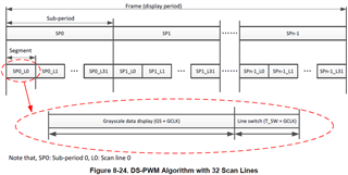
    The reason for why your image shows for a fraction of a second is that when LP5890 / TLC6983 finishes displaying a whole frame (display period) (see the datasheet capture below), it will not automatically start a new frame (display period) until the controller tells it to do so (i.e., send the VSYNC command).

    To maintain your static image on the display, you can try writing the same static image to both Memory BANK A and BANK B (Please check Section 8.6.1.1 Memory Structure Overview from the datasheet) and then sending the VSYNC command periodically.

    There are ways you can optimize your register settings to maintain the static image with the least controller resources, but that should be a deeper topic and we can talk about that later.

    Best Regards,

    Steven

  • Hi Steven,

    Thanks for your fast and thorough response.

    I have modified the test code (below) and it works well.

    The sync is being sent at approximately 24 times per second and there is no flicker on the display.

    Could you please give me some information on register settings to maintain the static image with the least controller resources? Whilst this technique will work for my application I would just like to understand any other options before I do more detailed design on a controller for the display.

    Thanks again,

    Matthew

    LED_sendSRAM(TOTAL_SCAN_LINES);
    sendSYNC();
    LED_sendSRAM(TOTAL_SCAN_LINES);
    sendSYNC();


    while(1) {

        sendSYNC();

        toggle_test_pin();

        for (delay = 0; delay < 25000; delay++)
        {

        }
    }


  • Hi Matthew,

    To maintain the static image with the least controller resources, the basic idea is to prolong the display period of one frame and therefore minimize the frequency that the controller needs to send the VSYNC command. To prolong the display period, you can try to alter settings such as your SCLK / GCLK frequency, SUBP_NUM and SEG_LENGTH register field. The settings will depend on your system spec requirements, such as

    • How long will you refresh the static image? With a constant interval or a random-length interval?
    • Do you have any refresh rate requirement?
    • What's the frequency of your SCLK?
    • What's your LED matrix size? Are there any LP5890 in cascading?
    • What's your PWM resolution requirement? 16-bit? 15-bit or less?

    The equation (3) in Section 9.2.1.3 Internal GCLK Frequency from the datasheet can help you understand how long the display period of one frame is.

    A handy tool to alter register settings is the Registers Map Generation Tool (You can find the download link from [Q2] in this [FAQ]).

    BTW, could you give me some information on the end equipment that you are going to build with LP5890?

    Best Regards,

    Steven

  • Hi Steven,

    Thanks - I am actually looking into lowering my SCLK frequency just now.

    I am happy to tell you more about the application, can I have your email address please?

    Regards,

    Matthew

  • Hi Matthew,

    You are welcome. I have sent you a friendship request on this E2E forum with my e-mail address attached.

    BR,

    Steven

  • Hi Matthew,

    Another comment for you:

    We would not recommend changing the SCLK frequency for the MSP430 version source code. The data and clock alignment is only verified for the current frequency setting. It will be difficult to change the SCLK frequency in this version of source code. 

    If you would like to change the SCLK frequency, we recommend using the C2000 version source code (LP5891Q1EVM-SW-F280039C) with C2000 Launchpad (Please refer to [Q2] from this [FAQ]).

    Best Regards,

    Steven