


Other Parts Discussed in Thread: BQ25731, BQ25792, ,
Hi Team,
I have questions regarding purposed block diagram shown below.
1. TPS25750S GUI has support for BQ25731 device so using this system standalone (without any MCU) should be possible? The article "e2e.ti.com/.../adding-usb-type-c-with-power-delivery-to-battery-powered-applications-smaller-faster-fewer-components" tells using an external MCU in BQ25731 system as mandatory. What am I missing?
2. Is it possible to add an external input source of 26V as shown in diagram?
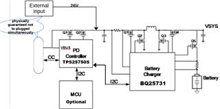
3. Usage of BQ25792 is not recommended for applications above 45W. Does this limit comes from the internal mosfets of buck boost converter? Sourcing a 45W system means the possibility of doubling the input current as it is the sum of the charging power and system power so a power requirement of 90W on the Buck boost converter. If the system works only with battery power (I mean no charging simultaneously) then using BQ25792 over 45W scenarios is also possible, right?
Could you help me clarifying this issues? Thank you in advance.
