This thread has been locked.

If you have a related question, please click the "Ask a related question" button in the top right corner. The newly created question will be automatically linked to this question.

TPSF12C3: Question on bias supply and surge protection for active EMI filter IC

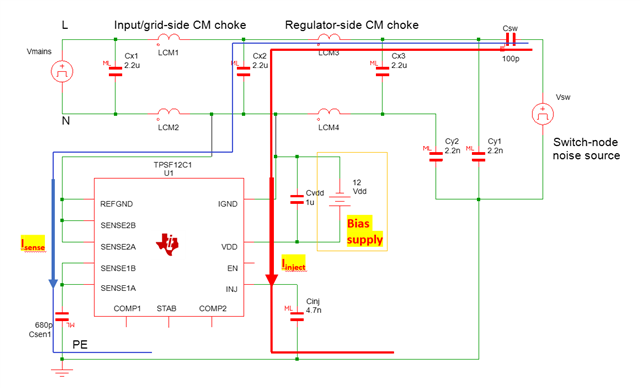
I made some modification on AEF IC connection. The modifications aim to move the AEF IC's bias supply to the grid side L/N instead of connecting to the PE GND/chassis so that the clearance between the AEF IC's bias supply and the AC grid L/N is not critical as original connection.

I am not sure if the modification can work?

  • I also have concern on lightning surge current passing through the AEF IC and TVS. As we know, the surge current would be very big (20~30Apk) and would cause hard failure of the TVS and IC.

    Not sure if anyone has any recommendation for surge protection?

  • Hi Martin, I replied on the technical article post - see here: https://e2e.ti.com/blogs_/b/powerhouse/posts/how-a-stand-alone-active-emi-filter-ic-shrinks-common-mode-filter-size 

    We can continue the discussion here or by email if you prefer.

    I copied the reply here as well for completeness:

    The surge test schematic does not show the MOVs, which are essential for clamping the input surge transient. With MOVs installed, the SENSE pins have internal clamps (adequate for the 680pF sense caps), and the external TVS as shown protects the INJ pin.

    In terms of the alternate schematic, sense caps are required to connect to the L and N power lines to detect the CM voltage disturbance (effectively the sum of the two voltages relative to chassis GND) and also to reject the line-frequency voltage and DM disturbance (the sensed voltage difference). Note that this AEF circuit uses a voltage sense, current inject (VSCI) topology - see white paper SNVAFJ9 for more detail.

    Regards,

    Tim

  • Hi Tim,

    Appreciate your clarifications.

    Please help to confirm my below statement on AEF. Since the INJ PIN of AEF IC is connected to the Y-cap and linked to the chassis, this AEF only affects the common mode (CM) EMI. For DM EMI, this IC doesn't have any help. I am not sure if my understanding is correct?

    Moreover, based on my circuit analysis, since the X-cap capacitance is much bigger than that of Y-cap or CSRC, so the X-caps can be shorted at higher frequency due to its low impedance. That's reason why the X-cap is usually shorted in CM equivalent circuit. If X-cap is shorted for CM noise, two terminals of Csense 1 and 2 which connects X-cap CX2 are also shorted together. The CM current (ICM) will be sensed by sense resistors inside the AEF IC through Csense 1 and 2. If we short two sense pins (SENSE 1A and SENSE 2A) together, we can also sense the same amplitude of ICM current. That's why I proposed to use only one CSENSE and then we can move the AEF IC toward L/N side in-stead of placing at chassis GND.

    We have some simulation circuits, right? Could we just simplify to short all SENSE1,2 together and use only one CSENSE which is connected to ether Line or Neutral? By this way, we can know if we can get the same result. If the results are same, we can go one step further that we move the AEF IC toward L/N side as I proposed previously.

    Best regards,

    Martin

  • Hi Martin,

    Tim is OOO right now.

    First, your common-mode current loop is not exactly correct.

    Most of the CM cancelation current is through CINJ and then through IGND GND that is referenced to Chassis.

    The sensing capacitors are not meant to conduct any significant CM noise current, (however there may be some negligible sensing current)

    You need the sensing capacitors on both L and N to sense CM voltage.

    The total L and N voltages are sensed, and then added together to eliminate the DM voltage. 

    Thus you cannot sense with just one connection, you need to sum them to eliminate DM noise.

    Hope this helps,

    -Orlando

  • Hi Orlando,

    Thanks for your prompt response.

    I know the main CM current is through CINJ to the chassis. In my previous discussion, I just wanted to indicate the CM current for sensing path.

    I still don't agree the AEF IC can help on DM EMI cancellation since the DM current path never go through the CINJ and chassis.

    To demonstrate all sense pins can be shorted together and use only one sense capacitor, I make some simulations based on simulated model from TI.

    The simulation results show the new connection and the origin have the same results. It is difficult to me to go further because I don't have detailed model of AEF IC. I will continue to work with my proposal that moving the AEF IC toward the L/N side so that I don't need to keep wide clearance between AEF related components and the primary side components of converter.

    Simulation for TPSF12C2 with shorted SENSE pins.pdf

    Best regards,

    Martin

  • Hi Martin,

    The DM currents can be large enough so that there is still significant ripple voltage across the X-caps.  Sensing only one line can result in the AEF IC responding to differential noise as though it were common mode noise. This would cause injection of common mode noise instead of common mode noise cancelation. 

    Ben

  • Hi Martin,

    If there are no other questions, can you please click on "resolved" to close the thread.  Thanks!

    Ben