This thread has been locked.

If you have a related question, please click the "Ask a related question" button in the top right corner. The newly created question will be automatically linked to this question.

UCC256404: UCC256404

Part Number: UCC256404
Other Parts Discussed in Thread: UCC28051, , UCC25600, UCC28056, UCC25640EVM-020, UCC28600, UCC28064A, PFCLLCSREVM034, TLVH431

..Is there part with power factor correction? My requirements AC to DC converter with power factor correction AC input 85V -265V Frequency 60Hz output 32DC @ 12.5A High efficiency.

Can I use below parts#

For PFC=UCC28051

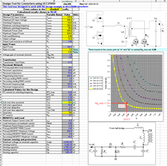
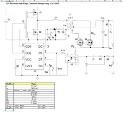
For Controller UCC256404

Please advice ASAP

Regards

Sam

  • Hi Sam,

    Yes, these can work. There is a newer PFC the UCC28056 which might be a better starting point. We actually have PMP9531 which uses the UCC28051, and UCC25600. The UCC25600 requires a separate bias supply and external gate drive. The UCC256404 integrates these functions. 

    I hope this answers your question.

  • Hi JCHK

    Thanks for the help

    I need help with below

    1. I used WEBENCH® Designer UCC28056 it will give me schematic and BOM ,shall i use WEBENCH Design or PMP9531 Ref design?

    2. UCC28056BEVM-296 Evaluation Module on page 17 has a  schematic which one is better for my application? 1 or 2

    3 I also used UCC28056X Design calculator it has schematic which one is better 

    3. Do you have MATCAD PFC?

    4. I am using  LLC UCC256404  controller with designed to pair with a PFC controller.  I used WEBENCH® Designer  it will give me schematic and BOM ,shall  i use WEBENCH Design or PMP9531 Ref design?

    5 UCC25640EVM-020 Evaluation Module page 8,9, has a schematic shall I used this one or PMP9531

    6 I saw  PMP31179 is it good for my application?

    Is there Mathcad for UCC28056

    How do i determine the Transformer ratio and calculation?

    How do I adjust the  32VDC out on PMP9531 design?

    Please advice

    Regards

    Sam

  • Hi Sam,

    1. I used WEBENCH® Designer UCC28056 it will give me schematic and BOM ,shall i use WEBENCH Design or PMP9531 Ref design? *Webench is a good tool, but it does not always provide the best options. For example when I put in your requirements, I get the UCC28056+UCC28600 recommendation. But if I just use the output of a PFC stage, I several more options including the attached. Note: When you try this webench will provide recommendations using the UCC25630x series but we now how the UCC25640x series which is an improved version. 

    2. UCC28056BEVM-296 Evaluation Module on page 17 has a  schematic which one is better for my application? 1 or 2 *This EVM was designed to support up to 165-W. For higher power, you would need to modify it. 

    3 I also used UCC28056X Design calculator it has schematic which one is better  * The calculator will help you optimize your design. 

    3. Do you have MATCAD PFC? * Unfortunately no. We just have Simplis models and the design calculators. 

    4. I am using  LLC UCC256404  controller with designed to pair with a PFC controller.  I used WEBENCH® Designer  it will give me schematic and BOM ,shall  i use WEBENCH Design or PMP9531 Ref design? * It is really up to you. The UCC25640x series should be a simplier design as it integrates the gate drivers and more. 

    5 UCC25640EVM-020 Evaluation Module page 8,9, has a schematic shall I used this one or PMP9531 *PMP9531 is closer to your power level. The UCC25640EVM-020 was only designed to support up to 180-W

    6 I saw  PMP31179 is it good for my application? * This is a good find. I was not sure if you wanted to go with an interleaved PFC. While a little more complex, this will have lower ripple currents and better efficiency.

    Is there Mathcad for UCC28056 * Unfortunately no. We just have Simplis models and the design calculators. 

    How do i determine the Transformer ratio and calculation? * The datasheet has a step-by-step procedure, but the design calculator is easier to use. 

    How do I adjust the  32VDC out on PMP9531 design? The UCC28600 design calculator can help you do this.WBDesign51.pdf

  • Hi JCHK

    Thanks for the help

    I need help with below

    1. On PMP9531 Page 1 do  I have to change anything?

    2. page 2 it shows 28V@12.5A I used your UCC28600 design calculator it don't tell me parts values to change? PM9531 design used UCC25600D

      I need a help with how to, use the calculator change the parts values for PM9531

       Your web design shows 256403. There is another calculator UCC25640X can use this One?

    4. I still don't understand transformer design

    Please advice

    Regards

    Sam

  • Hi Sam,

    1. On PMP9531 Page 1 do  I have to change anything? *No. You can use the UCC28051. The UCC28056 is a newer version.

    2. page 2 it shows 28V@12.5A I used your UCC28600 design calculator it don't tell me parts values to change? PM9531 design used UCC25600D

      I need a help with how to, use the calculator change the parts values for PM9531

       Your web design shows 256403. There is another calculator UCC25640X can use this One? * The calculator is to help you make your own schematic. The excel calculator shows the components you need to select to support your input/output voltage and power requirements. 

    4. I still don't understand transformer design * Normally, you share the turns ratio an other parameters from the Excel calculator with your preferred transformer manufacturer and they help to optimize your design. 

    I hope this helps.

  • Hi JCHK

    Thanks for the help

    I need help with below

    1. I used the Design Tool UCC25600

    Shall  I use the circuit above with PFC UCC28051D or use the page 2 PMP9531 Design?

    2. TF PMP9531 (T1) part # is different compare to BOM and schematic?

    Regards

    Sam

  • Hi Sam,

    For your questions:

    1. The design calculator shows the generic values to use. PMP9531 uses bipolar transistors to make a stronger gate drive. I would follow PMP9531 as a baseline.

    2. I am not understanding this question. T1 is the same part on the BOM and schematic of PMP9531.

    I hope this answers your question.

  • Hi JCHK

    Thanks for the help

    I need help with below

     1.Filename: BOM-PMP9531RevC(001).xls
    Variant: 001
    Generated: 5/13/2014 1:36:21 PM
    SVN path: $URL:: $
    SVN rev: $Rev:: $
    85Vac to 265Vac to 28V/12.5A with TM-PFC

    REF T3 part # On the BOM see blow

    Schematic part #

    The above part # are different?

    I try to calculate the switching frequency PMP9531 (is this running at 398KHz)

    I read the data sheet for UCC25600D

    But I am not  understand how they Got the values R35=511 Ohms ?

    I used the calculator but it does not show 511Ohms

    What are the values on PMP9531 that I have to change in order get 32Vout @12.5A

    Please advice

    Regards

    Sam

  • Hi JCHK

    Thanks for the help

    I need help with below

    R35=511Ohms how they calculate the value

    I used the below formula but it did not work

    Please advice

    Regards

    Sam

  • Hi JCHK

    Thanks for the help

    I need help with below

     1.Filename: BOM-PMP9531RevC(001).xls
    Variant: 001
    Generated: 5/13/2014 1:36:21 PM
    SVN path: $URL:: $
    SVN rev: $Rev:: $
    85Vac to 265Vac to 28V/12.5A with TM-PFC

    REF T3 part # On the BOM see blow

    Schematic part #

    The above part # are different?

    I try to calculate the switching frequency PMP9531 (is this running at 398KHz)

    I read the data sheet for UCC25600D

    But I am not  understand how they Got the values R35=511 Ohms ?

    I used the calculator but it does not show 511Ohms

    What are the values on PMP9531 that I have to change in order get 32Vout @12.5A

    Please advice

    Regards

  • Hi Sam,

    Could you create two different threads for PFC and LLC related questions. 

    Also, I would recommend using UCC25640x controller for LLC instead of UCC25600.

    UCC25640x uses current mode control, and it has an adaptive dead time feature. Also, it does have integrated gate drivers too. 

    For designing your converter, please use the design calculator and EVM schematics as a reference (UCC256404 data sheet, product information and support | TI.com ).

    Let me know if you have any further questions. 

    Regards

    Manikanta P

  • Hi Manikanta

    The previous engineer told me to use PMP9531?

    LLC UCC25604

    My requirements AC to DC converter with power factor correction AC input 85V -265V Frequency 60Hz output 32DC @ 12.5A High efficiency.

    Which one is better PFC # UCC28056, UCC28064A  used with UCC256404?

    Do I have to use UCC25604 A or B it shows in the design calculator

    On Page 9 UCC25640EVM I can connect to PFC to without bridge rectifier connection?

    Thanks for the help

    Regards

    Sam

  • HI Sam,

    Mani is suggesting the UCC256404 as it integrates the gate drivers and other functionality which can help to simplify the design. 

    With respect to the right PFC it is up to your application needs the UCC28056 will be a lower cost and simpler design. the UCC28064A will cost a bit more but will have better efficiency and ripple. 

    We only have the UCC28064A available. Are you asking for the UCC28056B? Here are the differences between the different UCC28056 options

    If you are connecting the EVM to the output of a PFC, there is no need for a diode bridge. 

    I hope this helps.

  • Hi Mani 

    I am using UCC256404A.

    Do i have to change the values On the spread sheet Raw # 103 and 104

    or use as its is

    Raw # 32,33,34 are input to the LLC from PF # UCC28056?

    Please advice

    Regards

    Sam

  • Hi Sam,

    Do i have to change the values On the spread sheet Raw # 103 and 104

    You need to update these values form the Gain curve. Please see the comments next to these rows.

    Raw # 32,33,34 are input to the LLC from PF # UCC28056?

    Yes, Thats correct.

    Regards

    Manikanta P

  • Hi Sam,

    Please see the modified design calculator.

    Regards

    Manikanta PSAM_3463.UCC25640x Design Calculator Rev4.0 (1).xlsx

  • Hi Mani

    Thanks for the help

    Please keep the ticket open

    Regards 

    Sam

  • Hi Mani

    What is the Bias winding voltage and current i could not find in spread sheet?

    Please advice

    Regards

    Sam'

  • Hi Sam,

    Please see the below picture for bias winding number of turns. These turns are determined assuming the bias winding voltage is 15V. Also, the current taken by the controller is very small compared to output current. You can assume a current rating of 0.1A for the bias winding.

    Regards

    Manikanta P

  • Hi Mani

    How do i down load Simplis?

    Can i Use simplis model to simulate both UCC256404 and UCC2851?

    Is it possible to integrated both to-gether and run the simulation

    Regards

    Sam

  • Hi Sam,

    You can get Simplis here: https://www.simplistechnologies.com/ unfortunately, it is not free.

    We do not have a released Simplis model of the UCC28051, but we do for the UCC28056.

    What you will like about Simplis once you get used to it is that you will find it is a much faster simulator that is well suited for simulating a full system-level schematic. 

    Regards,

  • Hi JCHK

    Thanks

    Sam

  • Hi JHCK

    Can i Use simplis models to simulate both combined UCC256404 and UCC28056B?

    Regards

    Sam

  • Hi Sam,

    Yes. This is why Simplis is a popular simulator.

  • Hi JHCK

    Is it possible send me both combined UCC256404 and UCC28056B simplis model

    Regards

    Sam

  • HI Sam,

    I am sorry I misunderstood your question. We do not have a combined UCC256404 and UCC28056B Simplis model. You would need to import each model into Simplis and connect them together as you would in your application.

  • Hi JHCK

    Thanks

    Sam

  • Hi Mani

    On the UCC256404A LLC loop plot & Load Transient Validation tool (3463.UCC25640x Design Calculator Rev4.0.xlsx)

    VDD and Vo are connected together with 32VDC?

    It does to give values for RLower?

    no values or U1? Can I Use TLVH431ACDBZT on the PFCLLCSREVM034 ref design

    Can I use same loop circuit on the REF design?

    What is the audio Susceptibility plot?

    Please advice

    I build  the T/F thanks for the help

    Regards

    Sam

  • HI Sam,

    Here is the feedback circuit that you could use for your application.

    Since TLVH431 max cathode voltage is only 18V which is more than your output voltage, you need to use zeners as shown in above picture.

    For all other component values in the above schematic, you can use same as EVM schematic (PFCLLCSREVM-034 User Guide (ti.com)) values.

    Audio susceptibility plot give the bode for output to input voltage transfer function.

    Regards

    Manikanta P

  • Hi Mani

    Thanks for the help

    UCC256404A is this constant current and Voltage? 

    Not on the data sheet

    What is acronym LLC (Local Controller)?

    Regards

    Sam

  • Hi Sam,

    The control methodology of the UCC25640x is similar to the current control of a PWM converter.

    You can use this controller for any type of control whether it's a output current or output voltage which depends on the application.

    The EVMs schematics controls the output voltage. 

    We do have reference designs that controls the output current (https://www.ti.com/tool/PMP40766 ) which is required for battery charging and LED driver applications.

    Since LLC resonant converter uses magnetizing inductance (Lm) and resonant inductor (Lr) and resonant capacitor (Cr) as part of the resonant tank, it is called as LLC converter. 

    Regards

    Manikanta P

  • Hi Mani

    Thanks for the help

    Regarding the UCC28056BDBVR

    Digi key says UCC28056BDBVR discontinue?

    Mouser says part available 

    For calcula  
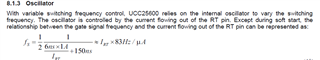
tion  I can use UCC28056X calculatorUCC28056X_Design Calculator.xls

    Please advice

    Regards

    Sam

  • Hi Sam,

    Could you please create a different thread for parts not related to the UCC25640x. The engineer who supports PFCs should be able to help you with this.

    Regards

    Manikanta P

  • Hi Mani

    Can I use UCC256404A in military application?

    If there is a Part # for military application

    I could not find any information

    Please advice

    Regards

    Sam


  • Hi Sam,

    Yes, it can be used in military application.

    Regards

    Manikanta P