I am using UCC21710 to drive 2 SiC MOSFETs in parallel. Based on the discussion in another link of e2e (https://e2e.ti.com/support/tools/simulation-hardware-system-design-tools-group/sim-hw-system-design/f/simulation-hardware-system-design-tools-forum/1219348/tida-00917-tida-00917/4612886#4612886) I have incorporated the common mode choke at the Gate drive circuit as shown in the picture below. The application is a grid-connected inverter. 12 KVA, DC Bus of 850V, 50kHz. The SiC MOSFETs used are NVH4L040N120SC1 (from ONSEMI).
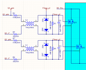
Fig.1
The gate drive circuit is as below (R14 will be kept 0 ohms, and in place of D3, 0 ohms will be used)
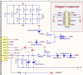
Fig.2
I have multiple questions regarding the connecting gate driver to SIC Mosfets.
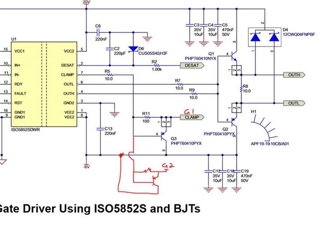
1) Should we connect the CLAMPI pin directly to both the gate pins of the SiC Mosfets (means shorting them (symmetrically in layout) and connecting them to the CLAMPI pin, or should it be connected before the COMMON Mode choke (i.e., between R7 & L1 and R2 & L2 in Fig.1) or should it be just before R2 and R7 (Gate resistors)?
I have done some LTspice simulations using the spice models for the gate driver and did the Double pulse test. If the CLAMPI pin is connected to the gate pin directly, the common mode choke seems to have no effect in current sharing, and if connected before, the CM choke does help in current sharing (if source layout inductance for 2 MOSFETs are different)
2) When 2 SiCs are paralleled, how to connect the OC pin (as DESAT protection) to both MOSFETs? Should one use the circuit shown in Fig.3 or Fig.4? I'm worried about the current sharing between the SICs. If different, the DESAT may not be detected at the proper time. For example, if the current through one of the SIC goes above desat limit value, and on the other MOSFET, it is below the limit, the effective voltage (parallel with some non-idealities) may be that of the SIC carrying a lower current. Hence, the DESAT may not be detected at the proper time.
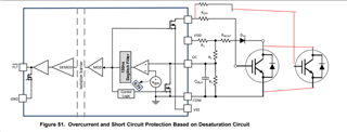
Fig.3
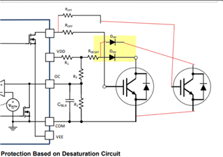
Fig.4
The SiC Mosfets are kept as close as physically possible.
3) Are there any recommendations you suggest incorporating into the Gate drive circuit?