This thread has been locked.
If you have a related question, please click the "Ask a related question" button in the top right corner. The newly created question will be automatically linked to this question.
Hi
I am using UCD3138CC64EVM-030A.
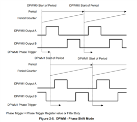
I want the PWM to operate in phase shift mode. First of all, I would like to implement it by a simple experiment, but I found some problems.
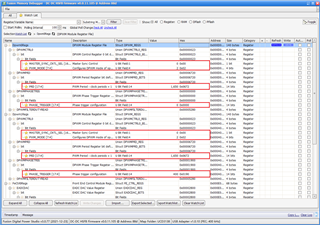
1. the MASTER_SYNC_CNTL_SEL bit is set to 0, master sync controlled by Phase Trigger Register.
2. the PHASE_TRIGGER bit of DPWM1 is set to 400, DPWM0 is 0.
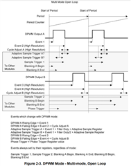
3. the DPWM_MODE bit is set to 2, Multi-Output Mode.
However, on the oscilloscope, DPWM0A coincides exactly with DPWM1A, with no phase difference.
So, I would like to ask if there is something wrong with my configuration?
Best Regards,
Jie
Jie,
Which channel do you want to be the master? Let me start by assuming DPWM0 is the Master here. See the following configurations.
Dpwm1Regs.DPWMCTRL0.bit.MSYNC_SLAVE_EN = 1; //configured to slave
Dpwm0Regs.DPWMPHASETRIG.all = ??;// fill the data you want.
LoopMuxRegs.DPWMMUX.bit.DPWM1_SYNC_SEL = 0; // Slave to dpwm-0
thanks
Hi Biss
Thank you very much for your answer.
As you described, I was able to successfully configure the phase-shifted PWM after adding these codes.
By the way, do you know how to associate Filter Duty with Phase?
Regards,
Jie
Hi Jie,
Dpwm0Regs.DPWMCTRL0.bit.MASTER_SYNC_CNTL_SEL = 1;//1 = Master Sync controlled by CLA value
thanks
Hi Biss,
Thank you very much for your reply.
Can you help me solve one more small question?
Dpwm0Regs.DPWMCTRL0.bit.MASTER_SYNC_CNTL_SEL = 1;//1 = Master Sync controlled by CLA value
However, for multi output mode, Filter Duty also determines the falling edge of DPWMAB.
So how can I ensure that the duty of DPWMAB is 0.5 during phase shifting
Best Regards,
Jie
Hi Jie,
A little confused about "So how can I ensure that the duty of DPWMAB is 0.5 during phase shifting", could you provide more details?
Regards,
Peter
Hi Jie,
Do you want DPWM1A to be slaved to DPWM0A and the phase shift controlled by the CLA value of DPWM0?
Or do you want DPWM0B to be slaved to DPWM0A and the phase shift controlled by the CLA value of DPWM0?
This is a different implementation. Could you draw the timing you need for better understanding?
Regards,
Peter
Hi Peter
Thank you very much for your reply!
When I set the phase shift to be determined by the Filter duty, I find that not only does the PWM phase change, but their duty changes as well.
I want DPWM1A to be slaved to DPWM0A and the phase shift controlled by the CLA value of DPWM0.
And the duty cycle should always be 0.5 for PSFB.
like this:
Best Regards,
Jie
Hi Jie,
You can reference the configuration of "Muti-Mode Open Loop" in manual. In this mode the edge of DPWM is determined by the event register.
Below configuration for your reference.
//Disable the CLA
Dpwm0Regs.DPWMCTRL0.bit.CLA_EN = 0;
Dpwm1Regs.DPWMCTRL0.bit.CLA_EN = 0;
//Mater slave
Dpwm0Regs.DPWMCTRL0.bit.MSYNC_SLAVE_EN = 0;// Master
Dpwm1Regs.DPWMCTRL0.bit.MASTER_SYNC_CNTL_SEL = 1; //Slave
LoopMuxRegs.DPWMMUX.bit.DPWM1_SYNC_SEL = 0; //0 = DPWM 0 Sync (Default)
//Phase shift is triggered by CLA
Dpwm0Regs.DPWMCTRL0.bit.MASTER_SYNC_CNTL_SEL = 1;//1 = Master Sync controlled by CLA value
//DPWM0 timing
Dpwm0Regs.DPWMEV1.bit.EVENT1 = 0;
Dpwm0Regs.DPWMEV2.bit.EVENT2 = period * 0.5;
Dpwm0Regs.DPWMPRD.bit.PRD = period;
//DPWM1 timing
Dpwm1Regs.DPWMEV1.bit.EVENT1 = 0;
Dpwm1Regs.DPWMEV2.bit.EVENT2 = period * 0.5;
Dpwm1Regs.DPWMPRD.bit.PRD = period;