Hi
Could you help check the TPS23754 schematic and any need to adjust
At present, when the power is turned on, D14 is always on, and when measuring GATE, there is no output at all.
This thread has been locked.
If you have a related question, please click the "Ask a related question" button in the top right corner. The newly created question will be automatically linked to this question.
Hi Gareth,
Please refer the feedback as below.
Regards,
Ben
Hi Ben


CTL Waveform
Gate still has no output.
Hi Gareth,
Thank for your feedback.
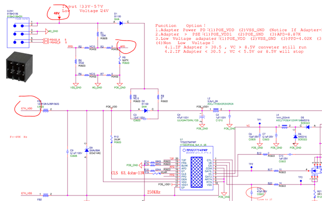
May I confirm with you what is the input supply source of TPS23754 now?
Could you check the power source is from ETH_VDD(RJ45) or 48v adaptor?
Could you capture the waveform of ETH_VDD1 APD and APD whether they are under UVLO threshold or not?
May I know whether it has failure rate or it will happened for every single board? Thanks.
Regards,
Ben
Hi Gareth,
Is the failure behavior happened with adaptor input voltage 33v only? Have you tried to increase the adaptor voltage whether the gate is still no output?
If you provide the PD power with POE injector, whether it works well.
In some case, we have saw the mosfet damage at secondary side and it will induce the pwm controller cannot work normally. Could you help to check whether output capacitor has been short? Thanks.
Regards,
Ben
Hi Gareth,
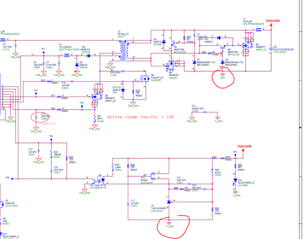
Can you help to confirm the P_GND and GND connected together? Thanks.
Regards,
Ben
Hi Gareth,
These two ground should be the same voltage level. Please connect it together and test it again.
Regards,
Ben
Hi Gareth,
Not this two ground. I mean the P_GND and GND connected together. Both of these two ground should be the same at secondary side.

Regards,
Ben
Hi GARETH,
Thanks for your confirm.
Seems we checked multiple potential reasons to cause PWM CTL stop. May need you help to check more cases that could cause it:
1. The PD is still in inrush state by some mistakes: you may check the voltage between RTN-Vss; but sometimes it is hard to know whether the inrush is ended or not.
2. There is a overheat issue: check the case temperature of the PDIC.
3. There was something happened before, which damaged the PDIC: you may see a high power dissipation from the PSE or bench power supply; but sometimes there is very low power dissipation after failure.
Best regards,
Diang
Hi GARETH,
Thanks for your test.
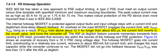
Do you see RTN-Vss having a constant high voltage or voltage pulses? If it is pulse voltage is with 12V and lasting 400us. It could be an overload fault.
You should check the ACF circuit very carefully if it is an overload fault. You can start with disconnecting the gate drive circuits on the secondary side and short their gate-source to run the two FETs in body diode mode.
Best regards,
Diang
Hi GARETH,
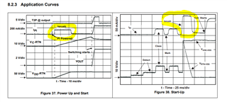
Is VSS-RTN a constant voltage or it is a pulse voltage? If it is a pulse like below, then you may have a overload/short-circuit fault.

If it is a 0.39V constant voltage, considering a 0.5-Ohm resistance of the internal hotswap, the current flow the hotswap is 0.39/0.5= 0.78A. It is a considerable current that could cause some parts to be overheated if no load is present.
Could you measure the inrush current during start-up? I would like to see when a ~0.78 A occurs.

Best regards,
Diang
Hi GARETH,
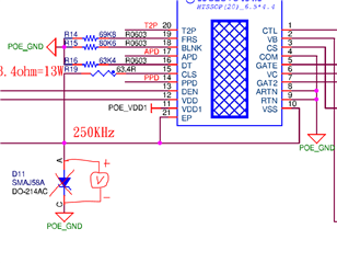
For the VSS-RTN measurement point, you can do it between D11. A TVS diode between RTN and VSS is usually not needed. Besides, make sure the APD pin is tied to RTN or the middle of the voltage divider (do not make it floating).
Please get a waveform to show the abnormal voltage if it is possible.
Best regards,
Diang
Hi GARETH,
Thanks for your test.
According to the VSS-RTN voltage, it looks like the hotswap has a short-circuit fault. But this normally leads to a hiccup mode which is different from your case.
I am wondering if you could check whether Q2, Q4, or Q6 was damaged.
Another cause could be the DC/DC startup too early to trigger the PSE protection. You may try to put a 47 uF AL capacitor in parallel with C6 to see if the PSE's inrush protection is the reason to cause the issue.
Best regards,
Diang