This thread has been locked.

If you have a related question, please click the "Ask a related question" button in the top right corner. The newly created question will be automatically linked to this question.

LM5022: Boost inductor creating ringing sound.

Part Number: LM5022

Hi TI Team,

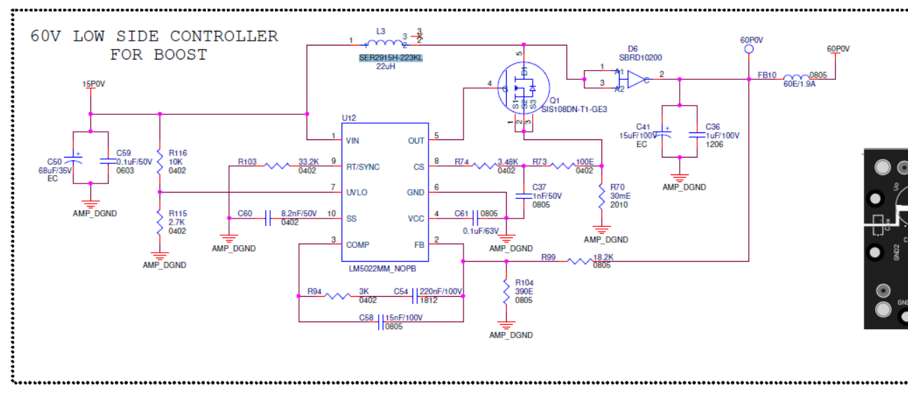
     I am using LM5022 to boost 15 V to 60V for my application. I will share my schematics below for your reference. 

1. If load increased after certain limit, inductor is giving ringing noise after that output current suddenly increased. kindly help us to solve this.

Inductor Spec: 

Part. No: SER2915H-223KL.(22uH)

Isat : 6A

DCR : 1.65mohms

Regards

Saravanakumar D 

  • Hello Saravanakumar,

    Thanks for reaching out to us via e2e.

    Which output current is this threshold that you need to cross to see that effect?

    It looks like that inductor is going into saturation.
    Some inductors are heating up and losing inductivity at much lower currents than the saturation current.
    Especially at higher temperatures the dependency between current and inductivity is no longer linear,
    and there will be a sudden drop of the inductance (even below the saturation current, which is rated at room temperature).
    At that point it is a vicious circle, less inductance, more current, even lower inductance, ...

    If possible, please try a different inductor.

    For further debugging we would need oscilloscope screenshots from the inductor current (maybe taken with a current probe)
    during normal operation and during the audible noise and high current.

    Best regards
    Harry

  • Hi Harry 

    We tried changing different inductor but same ringing noise exists. Measuring Inductor current is not possible now. Is there any other option we can try.

    Regards

    SK

  • Hello Saravanakumar,

    When I said different inductor, I meant to say a different model with different inductance, higher current rating, ideally from a different vendor.

    If you are using a completely different inductor, I would not expect the same noise.

    What about the current, does it also behave the same?

    Also, are you absolutely sure, that the noise is generated by the inductor? It can also happen that the capacitors will make such noise.

    You can try using a different power supply and a different load.

    All these devices are using switch mode converters internally, so in the end you are creating a chain of three such converters in a row.

    We have experienced that some combinations are causing such issues.

    To measure the inductor current, you van also inplement a sense resistor on the input side of the inductor (but after the input caps) and measure the voltage drop.

    Best regards
    Harry

  • Hi,

    Inductor spec is given below 

    MSS1260-333ML, Idc - 2.7A

    We checked, you are right  the noise is from capacitor. If the capacitor making such noise what will be the issue. 

    Regards

    SK

  • Hello Saravanakumar,

    When I looked at the schematic the first time, my first catch was that (especially the ceramic-) capacitors are too small.
    But then I got distracted by the inductor noise topic.

    You do not mention the load current, but I can see many components where the value doesn't look right.
    Did you ever calculate the components?
    Please keep in mind: when you change any component of the power stage you will need to re-calculate most of the parameters.

    - For a load current of more than maybe 100mA the chosen inductor is pretty big. For a load current of 1A I would expect something around 4.7uH or even lower.
    - The overall output capacitance is very close to the edge and does not leave any margin for tolerances, aging, etc.
    - Both, on the input and output side, please increase the capacitance of the ceramic capacitors.
    It is really essential, that you are using as much capacitance in ceramic, as possible. Electrolytic capacitors are too slow and can only act as kind of a second level buffer.
    Place the ceramic capacitors as close to the diode as possible and - in general - make sure that there are solid GND return paths.
    - The compensation network does not seem to fit very well. Especially C58 is much too big (this would usually range below 1nF.
    - As te output voltage is 4x the input voltage, you can also increase R74 for more slope compensation.
    - In the layout, do not surround the controller IC with the components of the power stage.

    Best regards
    Harry