This thread has been locked.
If you have a related question, please click the "Ask a related question" button in the top right corner. The newly created question will be automatically linked to this question.
Hi,
I have some questions about the mode switching of UCD3138.I hope to receive the support of the TI team.
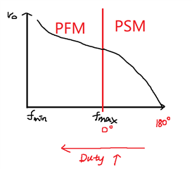
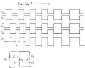
1. For phase shifting mode, when I set DPWM to open loop operation and the phase trigger is determined by the FILTER Duty.
I found that as the FILTER Duty increases, the phase between DPWM0A and DPWM1A also increases.
How to achieve a phase reduction between DPWM0A and DPWM1A with the increase of FILTER Duty?
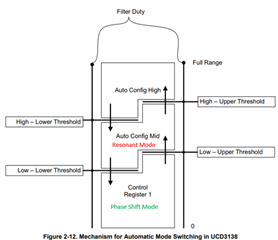
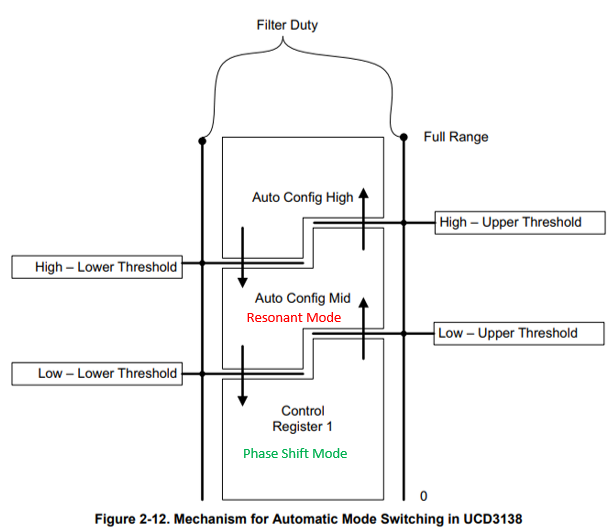
2. Will the previous working mode status be saved after the mode switch of DPWM?
For example, DPWM initially operates in phase shift mode, and enters variable duty cycle mode after DPWM0A and DPWM1A are shifted by 90 degrees.
Will the phase between DPWM0A and DPWM1A remain at 90 degrees after entering variable duty cycle mode?
3. For mode switching, changing the working mode of DPWM, etc., all are related registers of DPWM.
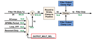
Can I change the register of the loop? For example, in different modes, the output YN of the filter will be multiplied by different coefficients.
Thank you very much again for TI's help.
Best Regards,
Jie
Hi Jie,
1. You can first refer to the paper "LLC performance enhancements with frequency and phase shift modulation control" for some inspiration.
https://ieeexplore.ieee.org/document/6803586
2. As shown in the diagram below, the switching mode is determined by Filter Duty. If Low- Lower Threshold is equal to Low - Upper Threshold, when you change from Resonant Mode to Phase Shift Mode, you will get the same phase shift as before.
3. I'm not sure what functionality you're trying to achieve, but I think it's doable just for mode switching.
4. Can you share more information about the system you want to implement?
Regards,
Peter
Hi Peter,
Thank you very much for your reply!
1. YES, The content in the paper "LLC performance enhancements with frequency and phase shift modulation control" is what I want to make.
Let me elaborate on my current confusion.
2. With your help, I was able to get DPWM to work in phase shift mode, configured as follows:
//Disable the CLA
Dpwm0Regs.DPWMCTRL0.bit.CLA_EN = 0;
Dpwm1Regs.DPWMCTRL0.bit.CLA_EN = 0;
//Mater slave
Dpwm0Regs.DPWMCTRL0.bit.MSYNC_SLAVE_EN = 0;// Master
Dpwm1Regs.DPWMCTRL0.bit.MASTER_SYNC_CNTL_SEL = 1; //Slave
LoopMuxRegs.DPWMMUX.bit.DPWM1_SYNC_SEL = 0; //0 = DPWM 0 Sync (Default)
//Phase shift is triggered by CLA
Dpwm0Regs.DPWMCTRL0.bit.MASTER_SYNC_CNTL_SEL = 1;//1 = Master Sync controlled by CLA value
//DPWM0 timing
Dpwm0Regs.DPWMEV1.bit.EVENT1 = 0;
Dpwm0Regs.DPWMEV2.bit.EVENT2 = period * 0.5;
Dpwm0Regs.DPWMPRD.bit.PRD = period;
//DPWM1 timing
Dpwm1Regs.DPWMEV1.bit.EVENT1 = 0;
Dpwm1Regs.DPWMEV2.bit.EVENT2 = period * 0.5;
Dpwm1Regs.DPWMPRD.bit.PRD = period;
As shown in Figure 1, after following the phase shift configuration above, if DPWM0A is connected to Q1 and DPWM1A is connected to Q4.
Then as the output voltage decreases and the filter duty increases, the phase shift angle between Q1 and Q4 will be greater, resulting
in a lower output voltage. This is an incorrect configuration.
So, for the above phase shift register configuration, I chose to have DPWM0A connected to Q1 and DPWM1B connected to Q4.
In this case, the phase between Q1 and Q4 is decreasing as the filter duty increases. This is working correctly.
This means that when the filter duty is equal to Low- Lower Threshold, the phase between Q1 and Q4 is also equal to 0.
Since the phase between Q1 and Q4 is 180 degrees at the beginning, I need to check whether the phase
between Q1 and Q4 remains 0 at this time after switching to resonant mode.
Regards,
Jie
3.
For resonant mode, the switching frequency is lowest at this time when the Filter Duty is at its maximum value.
Therefore, for the Filter Duty, the value of the filter output YN multiplied by Resonant Duty should be half of the value of the cycle count corresponding to fmin.
For the filter period, the value of the filter output YN multiplied by DPWM Period should be the corresponding period of fmin.
For phase shift mode, the switching frequency is fmax at this time. the phase between Q1 and Q4 should be in the range of 0 to 180 degrees.
How to ensure that when Filter Duty is equal to Low- Lower Threshold, the switching frequency is fmax at this time and the phase between Q1 and Q4 is 0?
Hi Jie,
Sorry for the late reply.
1. Why you arrange the different mode like this? why the mode change depends on Vo? what is the benefit or purpose for this?
2. Can you arrange the mode you want to achieve into the following format? Please identify where the different modes reside.
3. can you detail the timing you want to realized like this?
Regards,
Peter
Hi Peter,
Thank you very much for your reply!
1. I'm sorry my description is not very clear. Mode switching depends on the filter duty.
The meaning expressed in the figure is that as the filter duty cycle increases, DPWM from PSM mode to PFM mode, and the output voltage increases.
2. The mode switching is as follows
3. This is the main waveform of the primary switch.
Regards,
Jie
Hi Jie,
The main point is how to achieve the overlap of Q3&Q1 or Q4&Q2 in Phase Shift Mode and the Duty in Resonant Mode are all determined by the Filter Duty. as shown below.
Only by doing this, you can smoothly switch between different modes.
Regards,
Peter
Hi Jie,
OUTPUT_MULT_SEL can not be changed by auto mode switching way.
Regards,
Peter