- Ask a related questionWhat is a related question?A related question is a question created from another question. When the related question is created, it will be automatically linked to the original question.
This thread has been locked.
If you have a related question, please click the "Ask a related question" button in the top right corner. The newly created question will be automatically linked to this question.
Hi
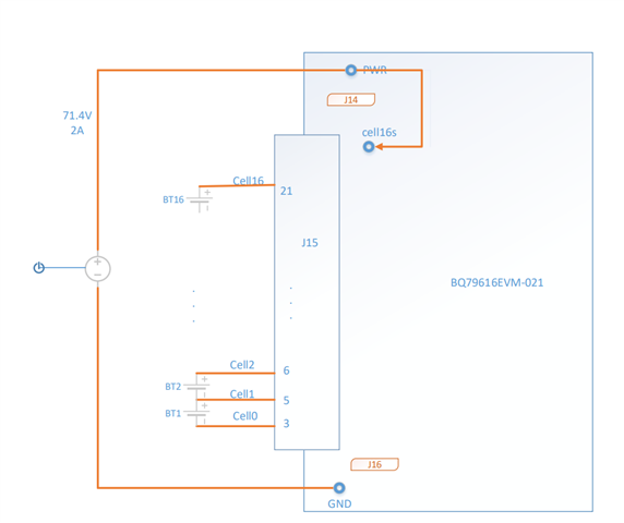
The customer test with BQ796161evm-021, usb2any, GUI. 16 3.7V cell, jumpers J14 and J16 are shorted. And short the cell16s and pwr signals, charging tool: 71.4V, 2A
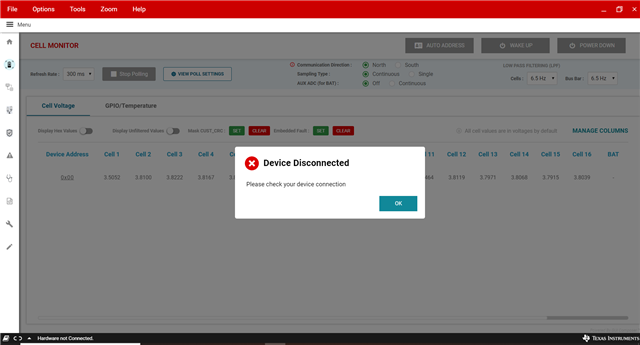
1, When turning on the charger, after about 10 seconds, the communication is interrupted, why?
2, If the cell16s and pwr signals are not shorted, the measurement of the 16th battery cannot be performed. Is the short circuit of these two signals correct?

Please give some suggestions.
Thanks
Star
Hi Star,
Please remove the J14 and J16 jumpers. Additionally, the power supply positive terminal must be connected to the "PWR" testpoint, and the power supply negative terminal must be connected to the "Cell0" testpoint since you are not using the resistor ladder cell simulator.
If this does not help with the issue, please send me a detailed diagram or picture of the setup so I can better diagnose the issue.
Best,
Andria
Hi Andria
Thanks for your help.
The customer if J14 and J16 are removed, the communication will still be cut off during charging.
Removing J16 the measurement of cell1 is inaccurate, plug in J16, and the measurement of cell1 will be accurate.
The test as below:
1, The positive of the 16th battery is connected to cell16 through pin 21 of J15, the negative of the first battery is connected to cell0 through pin 3 of J15, short-circuit pwr and cell16s, charge the positive pole to pwr, charge the negative pole to cell0s, and plug in J14 and J16 , no load
Test result: After a few seconds of charging, the communication is interrupted.
2, The positive of the 16th battery is connected to cell16 through pin 21 of J15, the negative of the first battery is connected to cell0 through J15, short-circuit pwr and cell16s, charge the positive pole to pwr, charge the negative pole to cell0s, remove J14 and J16, no load
Test result: After a few seconds of charging, the communication is interrupted. The measurement of cell1 is not accurate, the voltage will be about 0.3V higher
3, The positive of the 16th battery is connected to cell16 through pin 21 of J15, the negative of the first battery is connected to cell0 through J15, short circuit pwr and cell16s, remove J14 and J16, no charging, no load
Test result: the measurement of cell1 is inaccurate, the voltage will be about 0.3V higher
4, The positive of the 16th battery is connected to cell16 through pin 21 of J15, the negative of the first battery is connected to cell0 through J15, short-circuit pwr and cell16s, remove J14, plug in J16, no charging, no load
Test results: all 16 battery measurements are correct
5, The positive of the 16th battery is connected to cell16 through pin 21 of J15, the negative of the first battery is connected to cell0 through J15, short-circuit pwr and cell16s, charge the positive pole to pwr, charge the negative pole to GND, remove J14 and J16, no load
Test result: After a few seconds of charging, the communication is interrupted.
Please give some suggestions.
Thanks
Star
Hi Star,
Can you please send me some images of the setup your customer is using? You do not need to send an image for every test setup. Please just send images from one of the scenarios.
Thank you,
Andria
Hi Andria
Thanks for your reply.
Attached the figure.

1. Regardless of whether J14 and J16 are plugged in or not, the communication will be interrupted after charging.
2. If J16 is not inserted, the measured value of cell1 will be about 0.3V lower than the true value.

Waiting for your reply.
Thanks
StarHi Star,
Thank you for sending over this diagram. Unfortunately, I was hoping for a picture of the setup so I could see the actual board and check all your shunt placements.
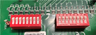
Please connect the negative terminal of the power supply to CELL0 and not GND when you are disconnecting J14 and J16. Also, can you please confirm for me that you are not using the resistor divider ladder? This means that switches S1 and S2 should be in the open position. I will attach an image below.

Best,
Andria
Hi Andria
Thanks for your help.
The customer follow your suggestion but still have the issue. the communication is interrupted during charge.
Attached the picture.

Please help check it.
Thanks
Star
Hi Star,
Please see the image attached below. After looking at the customer's J15 header, it appears as though the customer has the following connections according to the picture you shared:

With this setup, the customer does not have a connection for CELL0S or CELL16S. This is why removing the J14 shunt causes CELL1 voltage errors, and your customer has had problems with CELL16 and PWR, causing them to short the 2 points together.
Please have your customer address the J15 header connection issues, populating CELL0S and CELL16S. They can then remove J14 and J16, as well as desoldering the wire from the Cell16 test point to the PWR testpoint.
Additionally, the negative terminal of the charger should be connected to the CELL0 TP, not GND. Please also have your customer look at the BQ79616EVM User Guide for the EVM schematic to confirm any connectivity issues: BQ79616-Q1, BQ75614-Q1, BQ79656-Q1 Evaluation Module User's Guide (Rev. B).
Best,
Andria