This thread has been locked.

If you have a related question, please click the "Ask a related question" button in the top right corner. The newly created question will be automatically linked to this question.

LM138: External Capacitors

Part Number: LM138
Other Parts Discussed in Thread: LM317,

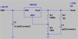
(1)Input bypass capacitor
Your recommendations:A 0.1-μF disc or 1-μF solid tantalum

(2)The adjustment terminal bypass capacitor
Your recommendations:A 1-μF solid tantalum or 25 μF in aluminum electrolytic

(3)Output capacitors
Your recommendations:A 1-μF solid tantalum or 25 μF in aluminum electrolytic


You say you recommend an external capacitor as above.
But I want to use ceramic capacitors.
Please give me advice for using ceramic capacitors.

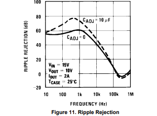
Also, you recommended a tantalum capacitor for the ADJ, which has low impedance at high frequencies.
Why do you recommend tantalum capacitors for VIN and VOUT?

I look forward to your reply.

  • Hello Ryosuke, 

    In the external capacitor section, I believe there is a mistype. 

    When it says, "large decrease in capacitance at frequencies around 0.5MHz"; we believe it is meant to say, "large decrease in impedance"

    With these older parts, there is typically a minimum ESR needed for stability. 

    Figure 8 provides us with the output impedance curves of the device. 

    Depending what capacitor you chose, and its impedance characteristics across frequency, you may need to add a resistor in series with the output capacitor. 

    Best,

    Juliette

  • Thanks for your reply.
    Is it okay to use ceramic capacitors for VIN, VOUT, and ADJ if the ESR shown in Figure 8 is secured?

  • Hello Ryosuke, 

    Before implementing the design, I would run bench measurements for your conditions. Ideally, yes if the ESR is matched for those components, the application should work; however, ESR and ESL vary across frequency and load. 

    LM317 May be a viable replacement for your application. 

    Best,

    Juliette

  • Thanks for the LM317 suggestion.
    I checked the LM317 datasheet.
    But I want 5A output.
    So unfortunately I cannot use the LM317.

    I'm thinking of using ceramic capacitors with the LM138. I don't use a capacitor on the ADJ pin. In that case, should I put a 3Ω resistor in series with the Vout ceramic capacitor?
    Also, is it OK to use only a ceramic capacitor for VIN?

  • Hi Ryosuke,

    Juliette is OoO today, she will be able to get back to you tomorrow, thank you for your patience.

  • Hello Ryosuke, 

    The ESR needs to provide the appropriate zero at around 500kHz to maintain stability. 

    However, having too large  of an ESR can affect the transient performance of the LDO:

     https://www.ti.com/lit/an/slyt151/slyt151.pdf

    Designing a PCB with a place for a Series resistance of 3 Ohms would be crucial for debugging. I would typically recommend starting in the mOhm range 3mOhms - 100mOhms to achieve a zero while keeping transient performance adequate. You would have to increase it or decrease it for your application. 

    Placing the capacitor above the resistor would also be recommended. 

    https://www.ti.com/lit/an/slyt194/slyt194.pdf

    We can take gain phase measurements to see the exact value we would need to ensure the part stays stable; however, we would have to order the parts and EVMs to support the request.

    As for the input capacitor, the datasheet does not mention needing a tantalum capacitor so a ceramic input capacitor may be adequate. It's typically good design practice to include a 1uF-10uF capacitor on the input. 

    Best,

    Juliette