This thread has been locked.

If you have a related question, please click the "Ask a related question" button in the top right corner. The newly created question will be automatically linked to this question.

TPS65262-2: Buck Overcurrent Protection During Startup

Part Number: TPS65262-2
Other Parts Discussed in Thread: TPS65262

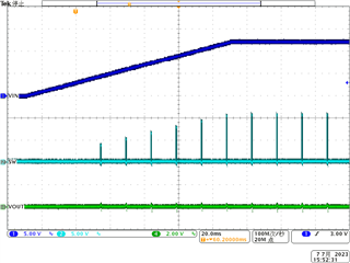
Is the buck overcurrent protection enabled during startup?  The attached scope plot seems to indicate that overcurrent protection or some other fault is triggered, with a subsequent 14ms hiccup time  (Buck1 3.3V rail is blue trace).  

In general, during what phases of operation is the buck overcurrent protection enabled and disabled?

I'm looking for a transient based PSPICE simulation that can help verify peak currents during startup.  Does TI have a solution for that?  

  • Hi Darin,

    Thanks for reaching out!

    • Would you please share us the schematic? Could you please share the waveform of inductor current of Buck3?
    • What's the status of Buck2 and Buck3? Can they startup and output normal?
    • Is the 12V input from a power supply or where? Why there is a platform and oscillation?
    • How is the load connected and what is the load current? How about if you try with a E-load?

    Thanks!

    BRs

    Lucia

  • I will work on those additional requests, but please answer my original questions. 

  • Control_Modules_Failures_Troubleshooting_FTR.pdf

    Here's some results from power cycling tests that caused a 3.3V rail to fail at cold

  • We are working on getting a scope plot that shows Buck 1,2, 3 rail voltages and the Buck 1 inductor current.

  • The 12V input is sourced by AC supply or a +12V battery.  The plateau and oscillation (or also called platform in your question) occurs due to the soft start behavior from the AC supply, the holdup capacitance on the +12V rail, and loads on the +12V rail.

  • Buck 1 (3.3V) is the only rail that failed on U22.  Buck 2 (1.35V)  and Buck 3 (1.1V) function normally.  It's unclear if they came up properly when 3.3V failed. Follow on testing will capture Buck 1, Buck2, and Buck 3 rails in one plot to verify.

  • Here's an updated result document with 90C test data as well.

    1234.Control_Modules_Failures_Troubleshooting_FTR.pdf

  • Hi Darin,

    Thanks for your detailed feedbacks. To answer your question:

    (1) The buck overcurrent protection is enabled during startup. Please kindly see an example shown below. The test condition is 12Vin and slew rate is 0.1V/ms. Load is from E-load. When overcurrent happened, during startup, it will still enter overcurrent protection mode. If an output overload condition has lasted for more than the hiccup wait time which is programmed for 0.5 ms, the device will shut down itself and restart after the hiccup time 14ms.  Each cycle the switch current and the current reference generated by the COMP pin voltage are compared which means it's cycle by cycle protection.

    (2) For Pspice model, actually TPS65262 support average model for loop response simulation, but no transient model available now. We can check based on EVM board to see measurement results from bench.

    (3) For the Vout waveform shown above, the hiccup off time is around 14ms. Would you please kindly check any overcurrent happened? Another way is to use an E-load instead to see whether 3.3 rail can start up normal.

     (4) BTW, is there large Cout for 3.3V rail? From the schematic, the total Cout is 2*47uF + 22nF. Please kindly correct me if not.

    Thanks! Kindly let me know if there is anything unclear. 

    BRs

    Lucia

  • Hello again Lucia,

    Another TPS65262 failed today in our product with the product power supply at -45C on the 12th cold power cycle.   This time the 5V circuit (Buck 1) failed.  The failure mode for both 3.3V/5V circuits (Buck1 on two different devices in the design)  is the same as reported before.  Hard failure upon applying AC to the product power supply.

    At 25C with the same power cycling test, there were no failures. This is with the product power supply.

    I'll attach a plot that shows the +12V ramp during cold and additional signals of interest around Buck1 circuits.   This is the 3.3V circuit.   

    I don't see anything out of the ordinary or concerning as to operation of the TPS65262.  The +12V ramp up is slow, and there is some chatter around 7.5V.  I don't see the BUCK1 signals chattering before during or after the +12V (source rail) moves up to final steady state value.  

    The reason for the slow ramp and chatter, is frozen electrolyte in the input and output caps of the power supply that sources power to the two TPS65262 devices. 

    Would it help to increase the inrush capacitor?  I don't see excessive inrush current on eut2_I3v3 (inductor output current).

    What about the ferrite bead (L9, L23) on the input of the input capacitors?  Is there any concern there?  The ceramic output capacitors should present low impedance to the Vin pins.

  • Correction, Would it help to increase the soft start capacitor? (not the inrush capacitor)

  • Hi Darin,

    We fully understand the high priority of this failure and I replied to you by email. Thanks!

    BRs

    Lucia