This thread has been locked.

If you have a related question, please click the "Ask a related question" button in the top right corner. The newly created question will be automatically linked to this question.

TPSF12C1-Q1: AC Model TPSF12C1 in PSpice

Part Number: TPSF12C1-Q1
Other Parts Discussed in Thread: TPSF12C1

Hi everyone I'm trying to do an AC analysis/frequency sweep for the TPSF12C1-Q1 using the model package "snvmca8.zip" from the TI product folder for the part.  Even if using the provided basic schematic the result in AC analysis do not match the gain across the part shown in the time domain simulation, it's pretty obvious.

Further, at the INJ pin shows a bias point about 0.7V node voltage, almost like the output is railing, when it should be Vcc/2 (near 6V for this particular simulation file).  That being said in the time domain plot its properly centered around 6V.

So...Is it possible to use this model to see the AC/frequency response from an injected voltage at a given node?  That's what I'm after here.

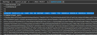
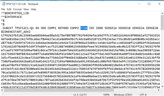
I did notice in another thread here on e2e there was an AC-functional model given for the 3-phase version of this part:

e2e.ti.com/.../tpsf12c1-q1-spice-component

Can that be used to simulate single-phase, leaving the other phases unconnected?

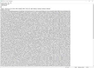
I tried running simulation file in that package and you get:

ERROR(ORPSIM-15461): Incorrect number of interface nodes for X_U1.

Thanks for your help!

  • Hi Peter,

    I'll ask our PSPICE expert to take a look.

    Regards,

    Tim

  • Thanks, appreciate it!

  • TPSF12C1_PSpice.zip

    Hi Peter,

    Please use the model attached. Please note that the AC and Transient models are not interchangeable.

    Regards,

    Rahil 

  • Hi Rahil,

    Thank you again much for assisting with this.  Am loading and running the simulation schematic as-is and am still getting this error:

    Hopefully you can read the screen-cap, but it's saying: "ERROR(ORPSIM-15461): Incorrect number of interface nodes for X_U1.", it's the same that happened when I tried the 3-phase AC model from the other thread.  I'm fairly new to PSpice, but it sounds like maybe there is mismatch in number of pins?  Do you know how to fix this problem?  Thanks!

  • Just putting it out there... but when selecting/right-clicking on the TPSF12C1 and choosing "View PSpice model" there is no "STAB" pin listed on the I/O of the model text.  Could that have anything to do with the error?

  • Hi Peter,

    Are you sure you're using the right .lib file? It should be under the TPSF12C1_AC folder

    I will attach the correct .lib file below, please replace it if needed

    TPSF12C1-Q1.LIB

    Regards,

    Rahil

  • Hi Rahil,

    Still no luck.

    I started fresh by extracting the TPSF12C1_PSpice.zip that you uploaded in this thread into a brand new isolated folder.  Next I copied the TPSF12C1-Q1.LIB that you attached in your post over the .lib file already in the folder just to make sure.  I loaded the "tpsf12c1_ac.opj" project file in PSpice, as normal, and it still doesn't show the STAB port in the model text, or run the AC simulation without the mismatch error.

    It does say a message window (attached snapshot) that it has updated parts, not sure if that has anything to do with it or not.

    Thanks,

    Peter

  • Hi Peter,

    I'm opening the file on my side and it runs perfectly. Can you please delete the folder you made, re-extract the TPSF12C1_PSpice.zip into an isolated folder, open the TPSF12C1_AC folder, open the TPSF12C1-Q1.lib file and send me a scree shot? 

    Regards,

    Rahil

  • Ok did that, attaching the snapshot.  Hopefully you can read it, but the STAB port is definitely there.

  • Have discovered that when I open the project with PSpice that .lib file suddenly doesn't have the STAB pin any more.  I have "A/B"'d this a couple of times.  Made brand-new folders, re-extracted, etc...

    Every time PSpice loads up, it puts up that indicator window that it's updated the models to the latest from TI..is it possible that it's changing it automatically due to that?  Is there a way I can disable that auto-update and try it?

    Thanks,

    Peter

  • To update: I have tried pasting the original .lib file (the same one you uploaded here as well) over the .lib file, in the folder *after* loading the project and letting PSpice establish, and now the simulation runs.  So it seems to have something to do with loading the project that it overwrites the .lib file with the original pinout for the TPSF12C1, with what it thinks it should be.  Any idea what could be causing this?

    Thanks again,

    Peter

  • Hi Peter,

    Not sure what would be causing that problem, I will do a bit  research on my end to figure that part out. It could be a possible directory issue. Glad to hear it's working for you now.

    Regards,

    Rahil

  • Hi again,

    Am I doing something wrong, or does this AC model only work for injecting a signal on the "STAB" pin, as how the provided PSpice schematic is configured?  I would like to be able to place a common-mode AC signal anywhere (for example where the regulator normally is) and see the resulting attenuation (on the line side, or at the injection point, for example) and see the difference with and without the TPSF12C1.

    Thanks,

    Peter

  • Hi Peter,

    Injecting on the STAB pin is only for AEF loop gain. You could remove that injection and instead inject into the filter itself to see attenuation /insertion loss

    Regards,

    Rahil

  • Hi Rahil,

    That's what I was trying to do initially, moving that AC source elsewhere, but it became apparent that the SENSE pins don't seem to work (are they grounded internally for the purpose of this model?), and the loop is not closed.

    I was thinking if the STAB pin is just a single-ended input to the amplifier then could add a summing node (PSpice VCVS dependent sources) to produce the common-mode adding function.  Should this sort of arrangement work?

    Thanks,

    Peter

  • Hi Peter,

    You need to do it remove the inductor and capacitor and short the STAB pin to COMP2. If you're doing insertion loss create a circuit like this: 

    Use the formula DB(V(LINE1_IN)/V(LINE1_OUT)) to graph it.

    Regards,

    Rahil

  • Hi Rahil, thanks for your insight, I've tried this and it appears to be working now, and the SENSE pins functional to complete the loop.

    Cheers,

    Peter