This thread has been locked.

If you have a related question, please click the "Ask a related question" button in the top right corner. The newly created question will be automatically linked to this question.

UCC21710-Q1: Is external current buffer required for 2 parallel SiC MOSFETs (G3R30MT12K)

Part Number: UCC21710-Q1
Other Parts Discussed in Thread: UCC21710

Hi Team,

We have used UCC21710-Q1 for single SiC mosfet for our application. Now, we are planning to use same IC for 2 parallel SiC MOSFETs (G3R30MT12K). Can this IC used for 2 parallel SiC MOSFETs?

Please provide if you have any reference designs for 2 parallel SiC MOSFETs operation using UCC21710-Q1. 

Thanks and Regards

Umamaheswararao

  • Hello Umamaheswararao,

    Yes, multiple MOSFETs can be connected in parallel - however it would be appropriate to ensure that the total drive strength needed to drive all 2 FETs is enough.

    Please refer to the below e2e thread:

    UCC21710: UCC21710 CLAMPI pin connections for 2 parallel SiC MOSFETs (with CM choke at the gate circuit). - Power management forum - Power management - TI E2E support forums

    Please let me know if it helps or if you have additional questions.

    Best,

    Pratik

  • Hi Pratik,

    Thank you for your reply.

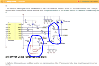
    As you referred the link, the BJT based current buffer is used for Gate Drive and Miller circuit highlighted with blue color circle, given below for your quick reference. 

    As per datasheet of the UCC21710-Q1, the peak drive strength is +/-10A.

    1. As per my understating, If I use 10Ω external gate resistor, the required drive current for two SiC MOSFETs is 2* ((15V+5V)/10Ω) = 4A. As per this,  UCC21710-Q1 IC can be used to drive two MOSFETS without using external BJT based current buffer, please correct me if my assumption is wrong. Please explain why gate drive current boosting circuit is required, 

    2. As per datasheet of the UCC21710-Q1, 4-A internal active miller clamp. Why we need external clamp circuit. How to calculate the required current rating for this miller clamp. Please provide the design procedure. 

    Thanks and Regards

    Umamaheswararao
     

  • Hi Umamaheswararao,

    A1. Yes, if the required drive current for both the SiC MOSFETs is less than the peak drive capability, I don't think you would need an external current buffer.

    A2. To implement the same CLAMPI pin for both the SiC MOSFETs you would have to short both the GATE terminals together which might cause issues like ringing propagation, etc. Therefore, it is recommended to use a separate FET for clamping the another GATE terminal of one of the FETs. An external miller clamp can be used if 4A isn't enough as well as mentioned in the image below:

    Hope this helps

    Best,

    Pratik

  • Hi Pratik,

    Thank you for your reply. 

    I am not clear about requirement of external current buffer circuit for UCC21710-Q1.

    How to calculate the peak drive current, If I use two G3R30MT12K parallel. 

    Please do the needful. 

    Regards

    Umamaheswararao

  • Hi Umamaheswararao,

    The requirement of external buffer depends on how long you plan to use the G3R30MT12K parallel FETs. The gate current required can be calculated as Ig = Qg/ Ton. Qg is given in the datasheet as 118 nC. Ton depends on the Fsw and Duty cycle you're driving the FETs at. You can then calculate the peak current and if the Ig of both the FETs combined exceeds 10A, you might need an external current buffer based on the additional current you would require.

    Hope this helps!

    Best,

    Pratik

  • Hi Pratik,

    Thank you for the reply.

    Please coniform the following

    If switching frequency is 50kHz, the operating duty cycle is 0.45 max and 0.05 min. The peak current at minimum duty cycle is (118nC/(0.05*(1/50kHz)) =   0.118

    As two MOSFETS are connected in parallel, the peak current requirement from the driver is 2*0.118 = 0.236A

    At the maximum duty cycle the required current is far less than the 0.236A

    It means that UCC21710-Q1 not required any external buffer circuit. 

    here i have couple of questions: 

    1. Is this 0.236A is peak current or average current?

    2.  If10Ω external gate resistor, the required drive current for two SiC MOSFETs is 2* ((15V+5V)/10Ω) = 4A., How this current can be link with 0.236A.

    Please clarify on the above two points. 

    Regards

    Umamaheswararo

  • Hi Umamaheswararao,

    1. 0.236A is the current that would be required to turn on the FET. Similarly, you can calculate the amount of current required to turn off the FET based on Toff.

    2. The source peak current that can be provided by the driver is IPK_SRC = (VDD-VEE)/(RDS(ON)_P + REXT), and the sink peak current is IPK_SNK = (VDD-VEE)/(RDS(ON)_N + REXT).

    For a 13V VDD & -5V VEE and 10Ω external gate resistor for both FETs,  IPK_SRC =  2*18/(0.6 + 10) = 3.39A and IPK_SNK = 2*18/(0.3 + 10) = 3.49A. 

    For a 33V VDD & -5V VEE and 10Ω external gate resistor for both FETs,  IPK_SRC = 2*38/(0.6 + 10) = 7.16A and IPK_SNK = 2*38/(0.3 + 10) = 7.37A.

    In either case, that should be sufficient for both the FETs since the peak source and sink ability of UCC21710 is 10A. You should be fine! 

    https://www.ti.com/lit/an/sluaaa2/sluaaa2.pdf?ts=1689691720962

    https://www.ti.com/lit/an/slla387a/slla387a.pdf?ts=1689691862479&ref_url=https%253A%252F%252Fwww.google.com%252F

    Hope this helps!

    Best,

    Pratik

  • Hi Pratik,

    Thank you for your professional answers. 

    Now, I understood that UCC21710 is not required any external buffer circuit for two SiC MOSFETs (G3R30MT12K).

    As per your suggestion, I will make the arrangements external miller clamp to avoid Gate signal oscillations. 

    Regards.

    Umamaheswararao