This thread has been locked.

If you have a related question, please click the "Ask a related question" button in the top right corner. The newly created question will be automatically linked to this question.

TPS5450-EP: tps5450

Part Number: TPS5450-EP
Other Parts Discussed in Thread: TPS5450

card.pdf

In the respective circuit a 3.8V is generated from +10V input. My queries are related to the noise reduction 

1. In the input rail an inductor ,capacitor combination is used. what is the purpose of that ? is it acting as a filter. Do we really want to connect such combination in the input side.

2. what should be the value of input capacitors , I have seen 4.7 uF combination at the input. can i use different capacitance ?

3. what should be the value of output capacitance?

4. How to reduce the ripple in voltage and current?

May be these are basic questions but i really appreciate if you could answer these questions.

Thanks in advance

/

  • Hi Arjun,

    Thanks for your inquiries and they are valid questions. I will also link further resources for your understanding.

    1. This is an EMI LC filter which filters differential noise coming from high dv/dt switching signal from the regulator to your source. This is usually for meeting CISPR EMI standards for automotive or industrial designs.

    2. CIN values depend on what kinds of ripple you want to achieve on your input line. I recommend reading the following article: LINK. It will also talk about your EMI and damping networks on the input as well. 

    3. Please see this reference for COUT: LINK.

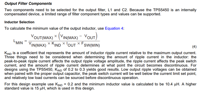
    4. Usually a combination of your COUT, COUT ESR and inductor ripple will affect your output ripple. See pages 12, 13 of the TPS5450 datasheet.

    Regards,

    Henry