This thread has been locked.
If you have a related question, please click the "Ask a related question" button in the top right corner. The newly created question will be automatically linked to this question.
Hi,
We are considering the circuit configuration shown in the attached image.
Could you please check if there are any problems with the constants of the peripheral components, FETs and inductors?
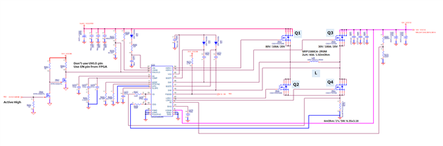
Q1:CSD19502Q5B, Q2:CSD19502Q5B, Q3:CSD17303Q5, Q4:CSD17303Q5, L:SRP1580CA-2R0M
capacitor constants:ex.)153p -> 15x10^3pF -> 15nF
resistance constants:ex.) 93.1KF -> 93.1kOhm(1%)
<Conditions>
LM34936RHFR
Vin=4.5V to 24V, Vout=12V, Iout=10A(max)
Best Regards,
Nishie
Hi Nishie,
Please use LM5176 Design Calculator (Rev. A) for a first check as these 2 devices are using the same regulation scheme.
Best regards,
Feng Ji
Hi Feng-san,
I will check with the documents you gave me.
I just want you to comment on whether there is any problem in selecting FET.
Should I check with the FET team instead of you?
Best Regards,
Nishie
Hi Nishie,
I would think Q3:CSD17303Q5, Q4:CSD17303Q5 are good choice.
Please reconsider Q1:CSD19502Q5B, Q2:CSD19502Q5B because:
1. Min Vin=5V means the gate driver voltage may be 4.5V, CSD19502Q5B will show much higher Rds(on).
2. Considering 24V max input voltage, 80V rating is a bit over designed. I think 40V or 60V will be good.
Best regards,
Feng Ji
Hi Feng-san,
Thank you for your support!
I will pass along information to my customer.
Best Regards,
Nishie
Hi Feng-san,
I received an additional question from a customer, so let me discuss it with you.
Since you said about Q1 and Q2 ”Considering 24V max input voltage, 80V rating is a bit over designed. I think 40V or 60V will be good.”.
Is there any problem if the Q1 to Q4 FETs are CSD18513Q5A?
Best Regards,
Nishie
Hi Nishie,
We can use CSD18513Q5A as a starting point.
Best Regards,
Feng Ji