A related question is a question created from another question. When the related question is created, it will be automatically linked to the original question.
If you have a related question, please click the "Ask a related question" button in the top right corner. The newly created question will be automatically linked to this question.
Thanks for reaching out. If this is a new design, I would like to point you to the new four-switch-buck-boost converters we have in our portfolio: the LM5177 and the even newer LM51772.
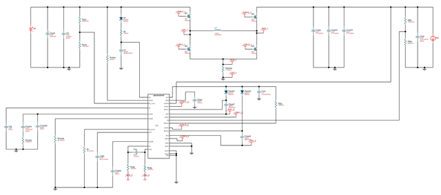
I've taken a look at your schematic and compared it to the proposal by Webench. I see you've chosen a smaller inductor, which would influence the inductor current ripple. Furthermore, your compensation circuit looks a little bit different, I'd like to point you to Switch-mode power converter compensation made easy for related questions. As long as you keep in mind that the chosen components in the compensation loop can only be approximations, and the actual tuning of said circuit should be done in a lab to keep the phase margin above 60 degrees. Which would assure system stability across component variation, drift and temperature changes.
For further considerations, please also look at section 8 of the LM34936 datasheet.
Thank you for your feedback! I appreciate the recommendation of the newer parts, unfortunately neither of these two are safe to spec in from an availability standpoint, as they are not readily available in DigiKey/Mouser and other places listed at octopart.com.
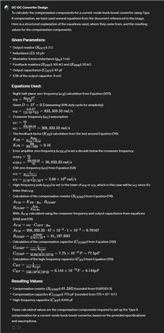
I pretty much used the design from Webench. Then, i took the LM34936 datasheet and your suggested document slup340.pdf and used ChatGPT to calculate the values for the 3 compensation components. I have actually made a Custom GPT specifically for DC-DC converter design, and then just attach my schematics and let it work from that. Below you can see the result, which is quite a bit different from the values calculated by Webench.
Could you please review this data and output from ChatGPT and from Webench and suggest to me which values i should build with as a starting point before we do the lab validation of the results?