This thread has been locked.
If you have a related question, please click the "Ask a related question" button in the top right corner. The newly created question will be automatically linked to this question.
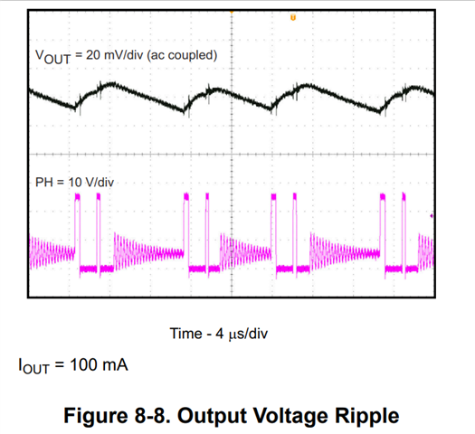
In the datasheet of TPS54202, as the waveforms shown in Fig8-8, it seems that the IC is operating in PWM mode in first two cycles and then switch to Eco-mode, can make a detail explanation about the three different states of the MOSFETs and how to decide the time of each state. Also, I do not understand the oscillation of the pink waveform.
Hi Steve,
1. The waveform you shared is in Eco-mode operation. Here the first pulse failed to provide enough power to output, so followed by another pulse to boost Vout. But still it's in Eco-mode. If you capture IL waveform, you could see the IL is discontinuous (DCM mode).
2. The oscillation happened when both FETs off, the residual energy in the L and SW parasitic capacitance drives the ringing that you see.
Thanks, but the first and second pulses are 500kHz? and how to decide the start time and end time when both FETs off?
How long is both the FETs in off state? What determines the end time in this state?
Hi Steve,
Since the device is not switching, the output voltage will start to decay as energy is drawn from the output capacitors to supply the load current. As the output voltage decreases, the control loop will sense the decreased voltage at FB and restart switching.