This thread has been locked.

If you have a related question, please click the "Ask a related question" button in the top right corner. The newly created question will be automatically linked to this question.

LP5024EVM: I2C NAKing

Part Number: LP5024EVM
Other Parts Discussed in Thread: USB2ANY, LP5024

Hi there,

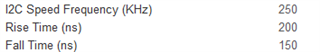
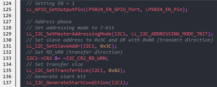
I'm trying to get this EVM board working using an STM32G071 Nucleo board. I've set up I2C with the following settings:

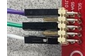
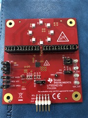
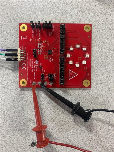
Here's what my jumpers look like:

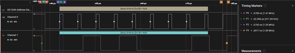
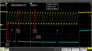
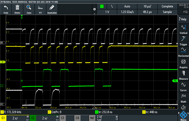
And here's what I'm seeing on my I2C lines (for the initial slave address + direction byte):

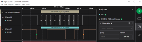
The communication looks good, I'm just not getting an ACK from the EVM board. I believe the jumpers on the board are set up correctly. I am powering with an external power supply set at 5V. I verified that the board works using the USB2ANY connector and the GUI, but I can't get it working using my current setup with the external micro board... Any ideas?

Thanks,

Evan

  • Hi Evan,

    It looks like there are 4 wires here. I think the blue and purple is for SDA and SCL. I wonder that what the white one and green one are for?

    BR, Jared

  • Hi Jared,

    Yes, the purple is SCL and blue is SDA. There are three others: The green is 5V coming from the microcontroller board, there is a wire underneath it connected to ground, and the white wire is the EN pin which is connected to a GPIO pin on the microcontroller board and is being set to high (shown in my code above). I was trying different setups with powering and changing J6 to try to get the EVM board to ACK, but I haven't found the setup that works for me yet.

    Hope this helps!

    Thanks,

    Evan

  • Hi Evan,

    I have tried 0x3C as the slave address to control LP5024 in broadcast mode. it can work on my EVM. So, I think it's not the hardware problem. So I suggest you to try the actions below:

    1. Please try to check the power of device, such as VCC, VCAP, VMCU, VLED.

    2. Please refer my hardware connection below first and try to send your command.

    3. Please try to change your slave address to 0x28 by controlling board in standalone mode to check if there is any ACK from board.

    BR, Jared

  • Hi Jared,

    I matched your jumpers you sent above and checked the voltages VCC, VMCU, and VLED and they are all at 5V. I tried both 0x3C and 0x28 as the slave address and I am still not getting an ACK. I double checked that the device was still working by using the USB2ANY setup and it does indeed work. Any other ideas I could try to get this working?

    Thanks,

    Evan

  • Hi Evan,

    Can you please measure the duration period of CLK high level?

    BR, Jared

  • Hi Jared,

    The high duration on SCL is 750ns

    Thanks,

    Evan

  • Here is a screenshot of the waveform with some measurements.

  • Hi Evan,

    I think it doesn't make sense. Please give me some days to simulate your signal in my office.

    BR, Jared

  • Hi Jared,

    Would you mine sending me a picture of what the waveform should look like? Is there something wrong with the waveform I sent? Should I see an ACK?

    Thanks,

    Evan

  • Hi Evan,

    Here is the waveform I captured, the T1, T2, T3 are just like your P0, P1, P2. Hope it can help you.

    Thanks and BR,

    Jared

  • Hi Jared,

    Does my I2C waveform look correct? Should I be getting an ACK?

    Thanks,

    Evan

  • Hi Evan,

    I think your I2C signal is correct and you should get the ACK. Can you please tell me the I2C waveform is from your software or from the board? If it's only from your MCU, please capture the I2C waveform from the board.

    BR, Jared

  • Hi Jared,

    I believe I discovered the issue. Here is a screenshot comparing the I2C coming from the USB2ANY (in white) versus the I2C from my microcontroller board (in color)

    As you can see, it looks like the I2C data is shifted by one bit when comparing the SDA lines. I'm wondering why this is the case? It looks like the USB2ANY is transferring 0x50 as a slave address instead of 0x28. This is not what is specified in the LP5024 datasheet. Any ideas on this?

    Thanks,

    Evan

  • Both of these were monitored on R1 and R2 on the EVM board by the way.

  • Hi Evan,

    I think it doesn't make sense. If the I2C data is shifted by one bit, I think the SDA falling edge will be shifted one bit too.

    1. I want to make sure the white signals are from the board side and the color signals are from the MCU, am I right?

    2. Could you please tell me how you connect your MCU to the board? Is there something between them?

    BR, Jared

  • Hi Jared,

    1. ALL of the signals shown were measured by probing the EVM board at resistors R1 and R2. The white signals were what was measured with the USB2ANY connected and the colored signals were what was measured with the micro board connected.

    2. I have wires connecting the micro board and the EVM board directly, there is nothing between them.

    Hope this helps, let me know if you have more questions.

    Thanks,

    Evan

  • Hi Evan,

    I am very sorry that I made a mistake for your waveform. The slave address of LP5024 is 0x28, but the slave address will be combined with a bit of W/R. So, the real signal send by MCU will be 0x50. It means 0x28 shifted one bit to the left and becomes 0x50.

    Therefore, you should change your MCU command from 0x28 to 0x50. Then, you will receive the ACK response.

    Sorry for the long delay.

    BR, Jared

  • Hi Jared,

    This fixed my issue. Thanks for the help!

    Best,

    Evan

  • Hi Evan,

    Glad to help you!

    BR, Jared