A related question is a question created from another question. When the related question is created, it will be automatically linked to the original question.
If you have a related question, please click the "Ask a related question" button in the top right corner. The newly created question will be automatically linked to this question.
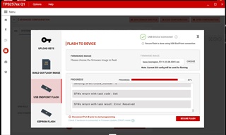
Dear Ziv, thanks for your email. i have another issure, when i download firmwave with TPS257XX-Q1 GUI, it seems some problem in my downlaoding process, would you like give me some comments about this issure? thank you in advance!
If you use End point download method, you should guarantee that EEPROM contains full flash program at the first time. It's used to validate key information. It means if it's one new IC without program, you should burn the program by I2C first. Then you can use Endpoint flash method.
I have a project use TPS25762 for PD output power supply design.
At present, "FULL FLASH IMAGE" is generated through GUI configuration, the bin file is burned into EEPROM through I2C programmer and then welded to the board.
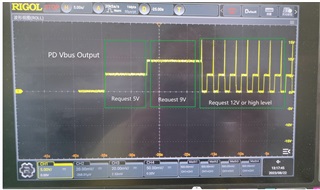
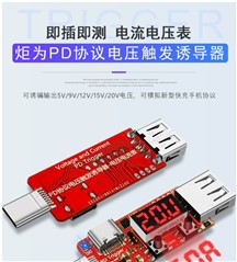
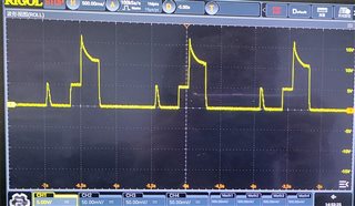
Then through the PD decoy test, TPS25762 can output 5V and 9V, but 12V, 15V and 20V can not output. PD decoy request 12V or higher voltage, but the output voltage has been jumping, 0V, 5V, 40V and so on.
PD decoy connected to other PD chargers can normally output the required voltage.
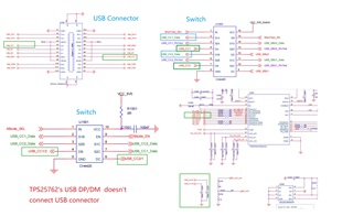
I have uploaded my schematic diagram, please help to check the cause, thank you very much!
i have another try. i connect TPS25762 to notebook which supports PD charge with standard TypeC cable. then i use the oscilloscope to capture the wave of the TPS25762's output. picture as below, pls help to analyse, thank you in advance!
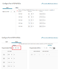
my problem has already been settled and thank you sincerely for your valid support.Currently,i can get 5,9,12,15,20V output but only get 4 outputs in one configuration.The configuration picture below ,pls check whether i can get 5 outputs in one configuration.