This thread has been locked.

If you have a related question, please click the "Ask a related question" button in the top right corner. The newly created question will be automatically linked to this question.

TUSB1044: Some basic questions about USB redriver

Part Number: TUSB1044

Hi team,

About TUSB1044 and USB redriver, I have 3 questions:

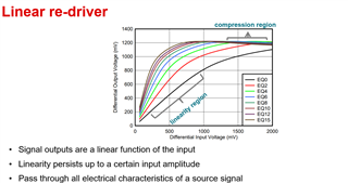
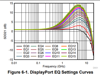
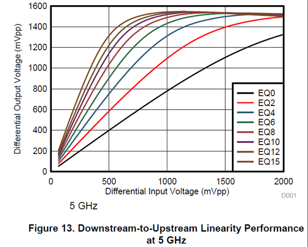
1. In the picture below, what's the difference between EQ0~EQ15? What is the meaning of the coordinates? (i.e. Differential input/output voltage)

2. According to USB3 and DP Alt Mode specifications, there exist certain electrical standards which require Type-C ports to meet. What are the standards about? Last week you said that the DP Rx/Tx side loss must be less than 8.5dB. Is this a part of the standard?

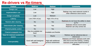
3. For Linear redriver,  what is its selling point? which features are vital to automotive customers? What is the advantage of our redriver in the market?

Best Regards,

Bengi Long

  • Bengi

    I will send out the training material once I clean them up. 

    For question 1, please see below. Differential input voltage is the input signal into the re-driver while differential output voltage is the signal out of the re-driver. The linearity range is the area which the output signal amplitude is almost a one-to-one ratio to the input signal amplitude. When using linear re-driver, you want to make sure the input signal amplitude is within the linearity range of the re-driver for best performance.

    EQ0-15 is the AC gain compensation which can be shown in this plot. You use EQ to compensate for the channel insertion loss, which reduces the ISI jitter. But as you can see from the above plot, higher EQ would also result in smaller linearity range.

    2. The USB Type-C refers to DP and USB3 specification for electrical standard. The specification defines the requirement for source and sink and verified using DP and USB electrical compliance testing using scope(Source) and Bert(Sink). USB also defines specific loss for source, sink, and cable to minimize any potential interoperability issue due to signal integrity issue. For link to the USB insertion loss white paper, please see this link, https://www.usb.org/sites/default/files/USB_3.1_Loss_Budget_Rev_1.0_-_2015-03-02.pdf.  

    3. For re-driver benefit, please refer to the table below

    Thanks

    David

  • Hi David,

    Thanks for your quick reply and detailed explanation. I have an extra question: As shown below, you said "the linearity range is the area which the output signal amplitude is almost a one-to-one ratio to the input signal amplitude." Now that the ratio is 1:1, the signal is not enhanced, how does our redriver compensate the cable loss?  Within my understanding, the equalization (compensation) means the output differential signal is 12dB (for instance) larger than the input differential signal. What is the definition for linear equalization?

    Best Regards,

    Bengi Long

  • Bengi

    You are thinking signal amplitude amplification (DC gain), but this is not the equalization purpose. The purpose of equalization is, 

    –Selectively boosts high-frequency data

    –Compensates for the media’s high frequency roll-off

    –Includes a high-pass filter that ideally has a frequency response exactly opposite to the media insertion loss that the equalizer is attempting to compensate

    So linear equalization is to maintain the original input signal characteristic as long as the input signal is within the linear re-driver linearity range and also provide compensation to the high frequency portion of the data.

    Thanks

    David