


Hi Apps,
I am a TI focus account DFA in the Americas.
We have a customer in my territory that is doing a high volume embedded design using an LCD & with our TPS65100.
They have a previous locked support question here:
From our customer:
We thought we had everything resolved, but recently had a couple of units apparently with the same condition.
(i.e. the TPS65100 powering up and then shutting down)
As before, the issue ‘followed’ the LCD module (not the board) – i.e. we move the module from board-to-board and it tracks the LCD.
Unfortunately, the 2 units somehow ‘corrected’ and are no longer exhibiting the issue…
(we power cycled 100s of times, high temp, low temp, high humidity, etc – cannot ‘make’ a failure)
The questions for the TPS65100 are as follows;
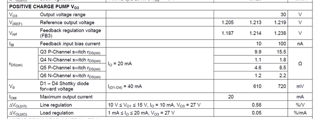
Snippet of the data sheet for reference, we’re talking about VO3 output;
(our values are, VO1=8.2V, V02=-13V, VO3=15V, VCOM unused)
The problem has recurred and they have additional questions:
Thinking of the load spike on VO3 from the LCD:
- What is the max current SPIKE that it can provide? I know this is dependent on the filter cap plus the rDS-on value of the FET switch…?
- Is there a max slew rate (i.e. mA/Sec) it can provide? i.e. what is the response time
- How does our VO1=8.2V affect VO3 output? (note the V01 range in the Line Regulation spec above and that we are below 10V). The data sheet only says that the output current may be ‘higher’ than 20mA depending on the delta VO1-vs-VO3…
The charge pump is capable of supplying a minimum load current of 20 mA. Depending on the voltage difference between VO1 and VO3 higher load currents are possible.
4. How does the IC/output respond to transitioning from a negligible (almost zero) load to a light load, of say 2mA.
5. Is there any negative side to increasing the output capacitance to 10uF (or more)?
Best Regards,
Blake Carpenter
TI DFA

