- Ask a related questionWhat is a related question?A related question is a question created from another question. When the related question is created, it will be automatically linked to the original question.
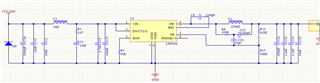
Hello, I have problem with LM5164. I used following schematics and PCB:
I had to use different layer for L (Bot) and IC (Top) with small overlapped area. So layout is not perfect (but on the other side not sooo bad):
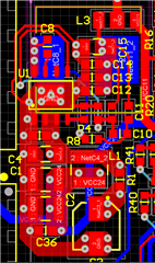
Layerstack: Top/Int1/Int2/Bot
Top=IC and the rest
Int1=solid ground
Int2=only FB trace
Bot=L and connection between L2/R8
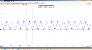
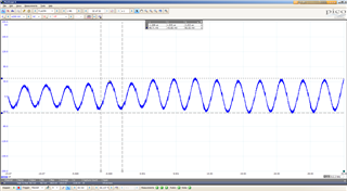
With 60mA load I am getting following result (AC coupled):
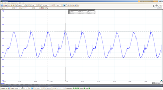
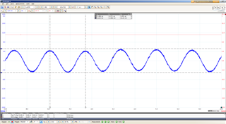
I have tried to remove C12+C14+C15 and solder short wire between R15 and U1.5 (FB trace). Trace is not ideal, but it is divided by solid plane and guarded by GND trace. Actual shot is from this state. There are only LDO and OP connected to the output of DCDC (no switching load). I am using 24V from LDO power source (30V/4A) w/o current limit. I also tried to skip input filter (no impact). Also there wasn't any visible impact for soldering short FB wire instead of trace on PCB (wire direct on IC/R15).
Inductor: Coilcraft MSS1210-224K (shielded, DCr=225mOhm)
I expected a bit worse result since inductor is direcly under IC/feedback etc. Before removing capacitors result was even worse. Under no load condition is Vpp>=1200mV. And voltage is oscillating with relative lowe frequency (~300 Hz).
From simulation @ Power Designer I expected Vpp to be around 80mV (f=33.2kHz then) and actual result is ~10 times more. Also DCDC converter is not much stable at all.
There is no another place for L. If this is caused by L at this place (I had to use similar layout few times before with LM76003 - and perfect results) - any sugestion how to make it better ?
Thank you !
R.