This thread has been locked.

If you have a related question, please click the "Ask a related question" button in the top right corner. The newly created question will be automatically linked to this question.

UCC28C43: FLYBACK 160V to 15V DC-DC Converter: TINA SIMULATION

Part Number: UCC28C43

Hi Team,

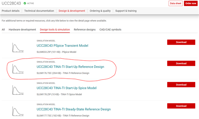
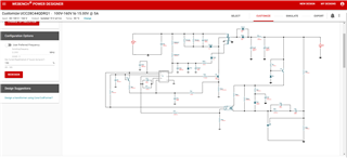
I am designing the flyback dc-dc converter using UCC28C43. I have used WEBENCH for the design and the same is given below 

I am simulating the same using TINA simulator. The simulation file is attached and results are given below 

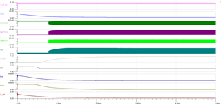
Output voltage is not getting as per design. Please check and suggest if any corrections are required. 

Thanks in advance for your support. 

Regards

Umamaheswararao

flybacksim_UCC28C43_uma.TSC

  • The most obvious error I see is that your flyback transformer is connected as a forward converter. There are several other errors I see and some of these may be coming from the Webench result. Can you download the UCC28C43 TINA Transient model and use this as your starting point? This model is working correctly and is close to the 100V<VIN<160V, VOUT=15V design parameters you require. I believe you should be able to modify this simulation file to get a working result close to your needs. You can also download and try TI Power Stage Designer and this will help with your power stage calculations and control loop design which you can then use the result to help modify the TINA simulation.

    Regards,

    Steve

  • Hi Steve,

    Thank you for your reply. I have done the simulation and working as per my design.

    Now, I have to design +/- 15V output using two separate flyback converters. Because I have to regulate the +15V and -15V output ports separately for different loads. 

    I tried the same in TINA using two flyback converters ( and two separate control ICs) with common input and output is connected bipolar connection (Converter-1 -Ve terminal connected to converter-2 +ve terminal and makes the common ground). But it was not working. 

    Please suggest. 

    Thanks and Regards

    Umamaheswararao

  • I'm not sure why your simulation is not working? If the two converters simulate correctly independently but produce an error when connecting the outputs together, maybe try not connecting the output GND references or connect them through a diode and/or low value resistor?

    Regards,

    Steve

  • Hi Steve, 

    Thank you for your reply. There is output GND issue and solved now.

    I have another quarry related to feedback signal. In the UCC28C43 datasheet, two different types of opto connections are mentioned. One is Pg22, FB pin is connected to ground and feedback is connected to COMP pin. The second one is in PG24, opto out is connected to FB pin and COMP.

    If FB is connected to ground, how output voltage is regulating. 

    I am not understanding which is better, please suggest. 

    Thanks and Regards

    Umamaheswararao

  • Can you please open a new E2E thread to start a new topic? Since the topic you originally wrote is now closed, I will close this thread. Thanks for contributing to E2E.

    Regards,

    Steve