This thread has been locked.

If you have a related question, please click the "Ask a related question" button in the top right corner. The newly created question will be automatically linked to this question.

BQ28Z610: BQ28Z610 automatic power up when attaching battery - recommendations

Part Number: BQ28Z610
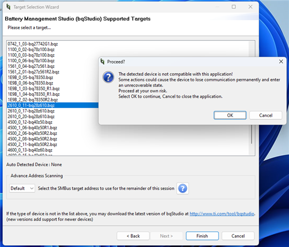
Other Parts Discussed in Thread: BQ25883, BQSTUDIO

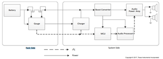
I am using the BQ28Z610 but not as a self-contained battery pack. Rather, a 2-cell lipo battery will generally be supplied by the user and plugged into the BQ28Z610.

There will also be a USB-C input for charging of the battery (although users may just plug in a fully charged battery instead, so USB-C charging is optional).

Hence, i want the BQ28Z610 to power up as soon as the charged battery is attached, turn on the MOSFETs and supply voltage to VSYS of the charger.

I note that the TI evaluation board has a switch from VBAT TO VPACK to temporarily allow the user to connect VPACK TO VBAT to bring the device out of shutdown.

i don't want that. There will not be an on/off switch.

If the battery is present, the device will be on. 

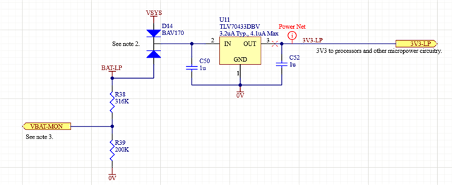
I do have a micro-power processor powered directly by the battery so the processor is powered continuously provided sufficient battery voltage is present.

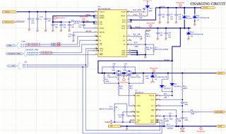
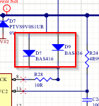
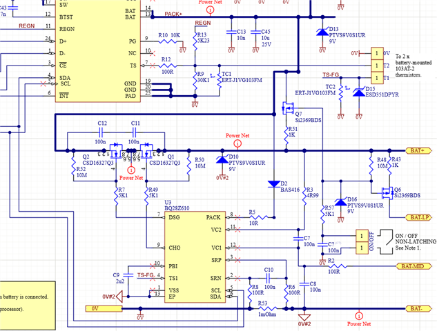
In the TI example circuits there is a diode from VPACK to the PACK terminal for powering the BQ28Z610. However, i do not think that is sufficient to power up the BQ28Z610 when a new, charged battery is attached. Indeed, the TI evaluation board has a switch that can be pressed that shorts VBAT to VPACK to bring the device out of shutdown.


Is it acceptable to also connect a battery directly from the positive battery terminal to the PACK terminal of the BQ28Z610?
The intention is the the BQ28Z610 is powered whether or not USB power is applied or just the battery voltage?
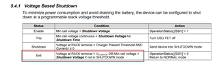
The processor could (possibly) put the fuel gauge into shutdown for minimum current consumption although I suppose that would make it lose its ability to keep an accurate battery capacity. The processor could also wake up the BQ28Z610. 

There will be some other circuitry attached to VSYS, which I would ideally like to disable to reduce power.

Question: Is there any way that can be turned off other than shutting down the BQ28Z610?
I don't think the BQ25883 can have its VSYS O/P disabled but i thought I'd ask while here. 

Question: Does the circuit below seem acceptable (re the diodes to PACK terminal of the BQ28Z7610)?

Question: Is there some particular reason why the Ti circuits show VPACK connecting to the PACK terminal rather than VBAT? If VBAT was connected, the device would always be powered, although it could still shutdown if needed.

Thanks for any assistance,

Derek

  • Hello Derek,

    Is it acceptable to also connect a battery directly from the positive battery terminal to the PACK terminal of the BQ28Z610?
    Question: Is there some particular reason why the Ti circuits show VPACK connecting to the PACK terminal rather than VBAT? If VBAT was connected, the device would always be powered, although it could still shutdown if needed.

    Connecting PACK pin directly to VBAT implies that the device will never enter shutdown state as long as Bat voltage is greater than ~2.5V. We have never recommended this before. The nature of PACK pin is to wake the device with the charger being attached allowing the device to enter shutdown mode when not in use even when the battery pack is fully charge.

    This thread should address these questions. Note that they are different devices but same principle as they both have high side switching protection. 

    Question: Is there any way that can be turned off other than shutting down the BQ28Z610?

    Can you re-phrase the question? The device can only wake from shutdown when a voltage at the pack pin is present.

    Also, I wanted to clarify that the BQ28z610 is PACK side implementation, not system side. Meaning the battery should be attached at all times. 


    For questions on the BQ25883, please open a new thread with the right part number so that the product experts reply your question. 

    Regards,
    Jose Couso

  • Thanks Jose - your reply is much appreciated.

     You said: “Connecting PACK pin directly to VBAT implies that the device will never enter shutdown state as long as Bat voltage is greater than ~2.5V. We have never recommended this before. The nature of PACK pin is to wake the device with the charger being attached allowing the device to enter shutdown mode when not in use even when the battery pack is fully charge.”

    Why will the circuit shutdown voltages be different just because I have an extra voltage input into the pack terminal (via a diode from VBAT)?

    The TI circuits show a diode from the pack terminal to the PACK pin. I am simply proposing an additional input to the PACK pin from VBAT.

    So with my suggestion: the higher of VBAT and VPACK gets fed to the PACK pin (minus a diode drop, but TI has that in the evaluation board). If VBAT goes too low surely that is still detected, and when a charger is plugged in it takes the PACK terminal high to bring out of shutdown.

    My circuit is not exactly as per the TI circuit, but I don’t see why it will not work.

    Thanks Jose,

    Derek

  • Hello Derek,

    Why will the circuit shutdown voltages be different just because I have an extra voltage input into the pack terminal (via a diode from VBAT)?

    The wake up condition from shutdown mode does not change. What I meant to say is that the device will always have PACK pin voltage greater than the Vstartup. 


    For instance, say you want to send the device into shutdown, but since the PACK pin is attached to the BAT voltage, the device will not enter shutdown. This is the trade off. 

    The TI circuits show a diode from the pack terminal to the PACK pin. I am simply proposing an additional input to the PACK pin from VBAT.

    It seems like it might work with the two diodes. The tradeoff is the device is cannot enter shutdown mode. You will need to ensure that not when FETs are off, the battery is not getting charge/discharge, meaning protections are working properly.


    My circuit is not exactly as per the TI circuit, but I don’t see why it will not work.

    Correct, it seems it might work. Please run some tests and let me know if this works for you. 

    Regards,
    Jose Couso

  • Thanks Jose for the clarification.

    I think I understand the possible issue now.

    I will ponder on that.

    one more question:

    FYI, I have a discharged battery attached. I haven’t programmed anything yet. But when I apply the charger voltage and hence voltage to the pack terminal, the MOSFETS are both turned off.

    Is this normal behaviour? I might have expected the charge FET to turn on. This is early days so haven’t done much probing eg to see if the charge FET turns on momentarily. ie should the charge FET at least attempt to turn on by default or do I need to program the device in some way first?I am certain this will be in the data sheet but you are sure to know the answer to that!

    I will let you know how I get on with the diodes.

  • Hi Derek,

    Are you doing these tests with your current schematic including the diodes? 

    The charge FET should be ON if FET_EN is set. See below


    In case the DSG FET is off, as soon as the gauge detects a current greater than the body diode protection threshold current, it will turn ON the DSG FET.


    Also, I forgot to mention that the charge pump uses PACK pin to drive DSG FET gate voltage. Your design might cause issues with charge pump. Leakage current in the DSG pin can affect the charge pump.


    Regards,
    Jose Couso

  • Hi Jose,

    I am out of the office until Friday so this is just a courtesy reply until I get back. I may well be able to add a mosfet switch instead which temporarily shorts the PACK and Bat terminals when a battery is attached. I will be able to respond properly on Friday, but in the meantime - Thank you.

    Derek

  • Hi Derek, 

    Yes, also you can reference to this thread for more insight in the design.

    Regards,
    Jose Couso

  • Thanks Jose,

    I have considered your suggestions and I think the following will be a little better and would like your thoughts:

    Capacitor C? (not yet designated) across the switch will temporarily turn on Q7 for a second or so, when the battery is attached.

    I may need to adjust the RC time constant which as shown is approx 10M x 0.1uF = 1s.

    This will switch the battery voltage to the PACK+ net and therefore to the PACK pin.
    (The switch is purely there for my debugging and will not be in the final circuit as the application does not have an on/off switch).

    This circuit also turns on Q6 which powers a low power mcu (the mcu is also powered by VSYS if present). Hence, at power up the mcu can drive the i2c bus and power up the BQ28Z610.

    However, I am having an issue with the battery software. I get the following error:

    FYI, in case it helps, when I start the software, the first I2C transaction (repeated 3 times) is:

    Also, how does one know which BQ28Z610.bqz target to choose?

  • Hi Derek,

    When the device is awake, it will display the target file BQZ, see below. 


    Try waking up the device before opening BQStudio. Apply a voltage at the PACK pin.

    Regards,
    Jose Couso

  • Hi Jose,

    Well, I am making some progress. Thank you. I can now communicate with the device.

    For now I am keeping the USB supply off and not enabling the charger (just to get the fuel gauge side working first). 

    I suspect my comms from my mcu was interfering so I stopped that.

    However at power up, I apply voltage to the PACK pin (for now by keeping the switch closed) but both mosfets are turned off. I can manually turn them on and off using the commands at the right hand side of the BQstudio software.

    So, comms is fine. I could of course turn the mosfets on manually using I2C commands, but I was expecting the discharge mosfet to turn on by default.

    The register values are are shown below. Battery voltage is measured at 6.91V (measured using a meter) and recorded as 6.891V by the device. 

    I am wondering if the 1K resistor R51 could be having an effect but I think I recall seeing a similar resistor in a TI circuit (although I may be wrong there).

    In any case, I am still wondering why the discharge fet is off when I apply a battery voltage and then start I2C comms.

    Thanks Jose.

    Derek 

  • Hi Derek,

    I believe the issue is FET_EN being 0 in the Manufacturing Status Register. See below.


    When FET_EN = 1, the FETs are Firmware driven autonomously. When FET_EN = 0, these are considered to be in TEST mode. 

    Regards,
    Jose Couso

  • Thanks Jose,

    I have programmed FET_EN =1 and that works. Thank you.

    I take it the default is for FET_EN = 0  so that the mosfets are off and one must program the device to enable them?

    I have a follow-up question re connecting to the BQ25883 but shall start a new thread for that as it is drifting from the original topic.

    I think this topic can be closed.


    Thanks for all your help, Jose - much appreciated.

    Derek

  • Hi Derek,

    Yes, by default FET_EN is off. This is so that you can test the FETs are turning ON and OFF properly. By writing 1 to FET_EN, it should be saved in data flash regardless if the gauge is power cycled. You can always toggle FET_EN.

    I am glad I have been helpful along the way. Please open new threads should you have additional questions.

    Regards,
    Jose Couso