This thread has been locked.
If you have a related question, please click the "Ask a related question" button in the top right corner. The newly created question will be automatically linked to this question.
Hi,
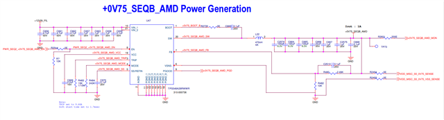
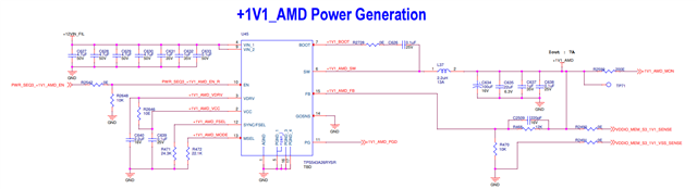
Currently, we are designing a buck converter using TPS548A28RWWR & TPS543A26RYSR this part number for our application.
We need your support to review the design, whether it looks ok?
We are having some queries and listed below,
please find the TPS548A28RWWR inputs below,
Vin -12V
Vout - 0.75V
Iout - 1A
Fsw - 800KHz
Mode - FCCM
For TPS543A26RYSR Inputs,
Vin -12V
Vout - 1.1V
Iout - 7A
Fsw - 500KHz
Mode - FCCM
Thanks,
Dinesh
I believe using a 15A device at 1A output may be confusing algorithm. Let me check
calculation sheet was not attached.
0.75V
Do you really need differential remote sense for a 1A output current?
Are you open to using TPS54J061 for the 0.75V output.
C670 (ss cap )should connect to VSNS- near pin 6, if using the remote sense
R484 R483 should connect to an AGND
C669 should connect to PGND.
C2510 is very large.
AGND should connect to PGND at one location.
See 10-1 page 40 for pcb layout example.
See figure 8-1 page 25 of datasheet for schematic example of agnd and pgnd
www.ti.com/.../tps548a28.pdf
Typically, inductor ripple is 10% to 40% of Iout. The tools have a range min and max inductance for control.
When using 1A, which is
Why use the TPS543A26 when the TPS548A28 was used for the 0.75V
Use the TPS548A28 for the 1.1V/7A
The pcb layout can be reused from 0.75V.
Instead learning two devices, there is synergy when using one device for both sockets.
Purchasing volumes will be greater when using for both sockets. Inventory is easier.
1.1V
On the high current supply, it is not clear you are not using the remote sense. Drawing GOSNS to the Cout
see figure 8-1 in datasheet for schematic example
an L of 2.2uH the equation must be incorrect in calculation. Webench estimates 1.2uH.
Similar to webench I get 1.0uH using the equations in the datasheet.
Use 2x100uF Cout.
Similar feedback on Agnd and pgnd.
R471 and R472 connects to agnd
C639 connects to agnd
C640 connect to pgnd.
see figure 8-23 for pcb layout example