This thread has been locked.

If you have a related question, please click the "Ask a related question" button in the top right corner. The newly created question will be automatically linked to this question.

UCC256404: Entering ZCS at 50% Load

Part Number: UCC256404
Other Parts Discussed in Thread: UCC25630-1EVM-291, UCC28180

Hello,

We are using UCC256404 LLC controller in one of our battery charging application. The excel tool prepared for the prototype is attached.

The reference schematic from UCC25630-1EVM-291 is used. The schematic is updated with the values from attached excel tool. The feedback circuit is same as EVM.

The transformer specification sheet is attached. The pins 14 and 17 are shorted. The pins 13 and 18 are NC.

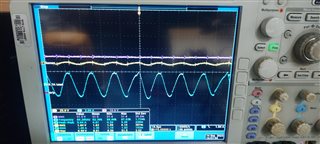
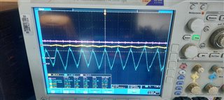
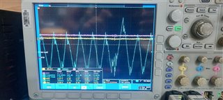
The LL/SS pin is changing to LOW when the output voltage drops to few volts once load exceeds >50% load (~10A).

Output voltage returns to nominal If the load is disconnected and connected back. Regulation is ok from no load up to 50% load (~10A @ 30V).


Please let us know is attached excel tool ok or any component values/compensation to be changed.

What might be the possible causes for entering ZCS at 50% of designed load?

Thanks & Regards,

Chethan K S

UCC25640x Design Calculator.xlsx30783-Half Bridge Tx.-Datasheet-Draft copy.pdf


  • Hi Chetan,

    You cant use this controller for such a high input voltage. Maximum recommended input voltage is up to 600V.

    I am curious how much voltage you are applying when you were doing the tests?

    Regards

    Manikanta P

  • Hello Manikanta,

    Thank you for the quick response.

    We tested at 800VDC input for LLC power stage.

    Regarding HV pin on UCC256404 LLC controller, 100Vac source is connected with full wave rectifier diode and a series 5k resistor similar to EVM reference design.

    The input voltage for our application comes from two phases with nominal 480Vac. The PFC front end stage is realized with UCC28180 CCM PFC controller. The output of PFC is 800VDC. The PFC proto is working ok for full load range 0 to 600W. We have external VCC option and 120Vac, 100mA source available in the end application for initial start up circuit. We may not use x-capacitor discharge feature.

    As of now we are testing LLC proto independently with 800VDC power source, 100Vac for HV pin and variable resistive loads.

    Please let us know your suggestions/review comments on compensation values. How to avoid LLC controller entering ZCS at <100% of designed load.

    Resonant inductor current captured at no load, 0.9A and 9.7A are attached for reference. Is switching frequency of 80KHz at 9.7A, 109KHz at 0.9A and 200KHz at no load expected? How the switching frequency is selected by the LLC controller? 

    Thank You.

    Regards,

    Chethan K S

  • Hi Chetan,

    This controller realizes the adaptive dead time by sensing the switch node voltage at the HS pin (800V in your case). This is exceeding the maximum recommend voltage of 600V.

    Could you share the switch node voltage and ISNS, LO, HO on the same waveform for these load values.

    Resonant inductor current captured at no load, 0.9A and 9.7A are attached for reference. Is switching frequency of 80KHz at 9.7A, 109KHz at 0.9A and 200KHz at no load expected?

    The switching frequency is purely determined by the LLC resonant tank values. 

    You can simulate your power stage using the simplis model given here:  https://www.ti.com/lit/zip/slum684

    Regards

    Manikanta P

  • Hello Manikanta,

    Yes, you are right. The HS pin voltage is exceeding maximum recommended voltage rating of 600V. We checked HV pin but missed HS/HO pin ratings in our internal review. Thank you.

    Please let us know Is there any way we can limit voltages on HS and HO pins of LLC controller by some additional circuit.

    Is any LLC controller available from TI for high input DC voltages like 800V to 1000V or do you recommend any other topology for our application?

    Any reference design available for using a DSP with isolated interfaces for PFC+LLC application?

    I will share switch node voltage and ISNS, LO, HO on the same waveform for different load values on Wednesday as we have festival holidays next week.

    Thanks & Regards,

    Chethan K S

  • Hi Chetan,

    You can use UCC25600 with external gate drivers which can support high input voltages.

    There are no external circuits that can be used with UCC25640x for operating higher than 600V since the HS pin is always needed to be connected to switch node.

    Regards

    Manikanta P