This thread has been locked.

If you have a related question, please click the "Ask a related question" button in the top right corner. The newly created question will be automatically linked to this question.

TPS6594-Q1: TPS6594-Q1 may not work normally when it is powered on at the begining

Part Number: TPS6594-Q1

Hello TI expert,

We use PDN_0C solution for TDA4 SOC. Currently we encountered a issue when PMIC is powered on.

Our ECU shall be about 1.5A @12V. However, for very few products,sometimes ECU may be about 47mA@12V when ECU is powered on.

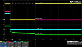
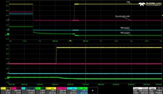
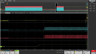
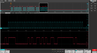
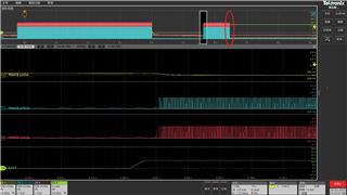
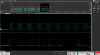
We try to find the root cause and find there is something wrong for PMICs. I test PMIC's pin and there is no output for PMICs while the power input is normal.

I try to reproduce it on the issue product for 3 times and dump all the registers of PMICs. I attached the logs here. Could you help review it and give your suggestions? Actually, there is something abnormal with the INT registers and others.


PMIC Register Log.xlsx

  • Hello An,

    please allow some time to look over this issue.

    But do you have scope shots at all when this occurred?

    BR,

    Nicholas

  • As the phenomenon occurs with probability, accurately getting the waveform is not very convenient.

    I try to test the VCCA and find it is normal all the time when the issue occurs. However, there is no other output pin wave snapshots currently.

    If you have some directions, I can try to reproduce it and record the wave. Pls let me know.

  • Hello An,

    I do have some follow up questions to better assist:

    1. Could you confirm whether all registers are in hexadecimal?
    2. Does this issue occur on startup or does the system run fine for a few (minutes or hours) before this issue occurs?
    3. Has the system been able to enter Low Power Standby mode properly?
    4. For the following, could you take a normal read from these registers again, when they're able to output?
      1. Register 0x83 RECOV_CNT_REG_1
      2. WD_ERR_STATUS 0x08 on page 4 of the register map
      3. WD_THR_CFG 0x09 on page 4 of the register map
      4. I BUCK3_CTRL doesn't look correct as it should be the one enabled instead of BUCK4_CTRL 

      5. 8h BUCK3_CTRL 30 20 20 20
        9h BUCK3_CONF 2d 2D 2D 2D
        Ah BUCK4_CTRL 31 A0 A0 A0
        Bh BUCK4_CONF 2b 2B 2B 2B

    Looks like you could be having a power problem on one of the rails or the system may be trying to enter a low power standby.

    At this point it's hard to tell without more information

    BR,

    Nicholas

  • Hello Nicholas,

    Replied as below:

    1.Hexadecimal.

    2.This issue occurs on startup.

    Then actually we have another issue, which is PMIC shutdown when it run a while. Pls refer to this topic and it is closed.

    3.I'm not quite clear about the System Low Power Standby mode. What does it mean and how to judge it? From my understanding, usually we will not use Low Power Standby mode. However, as I said before, Our ECU shall be about 1.5A @12V while it shall be about 47mA @12V at abnormal state.

    4.Read Register again at normal state.

    I2C address Register address Register value
    0x48 83 0
    0x48 8 30
    0x48 9 2D
    0x48 0A 31
    0x48 0B 2B
    0x4C 83 0
    0x4C 8 20
    0x4C 9 22
    0x4C 0A 20
    0x4C 0B 22
    0x12 8 0
    0x12 9 FF

    Then I would like to confirm more with you.

    Have you checked INT registers? Is it possible that some faults were detected during the power on self-test, causing the PMIC to actively shut off the output and enter a safety recovery state? There are some abnormal values in INT register in fact.

    Then for PMIC registers, we did configurate a few registers by TDA4. But for the issue, I think it occurs before TDA4 power on. We reproduced it, we just saw current stuck in 47mA, not current raised and fell. TDA4 shall not be powered on. That means we configurate nothing and it has to rely on NVM configuration.

  • Hello An,

    Thank you for providing the extra information, I just wanted to rule out the Watchdog possibly being an issue as well, it is not.

    After further review of the interrupts I can see that you're indeed having this problem at start up.

    From the interrupts, you are having BUCK4 short circuit on PMIC-A. On PMIC-B you're also having a LDO1 undervoltage and LDO4 short circuit.

    1. I know it may be difficult, but could you provide scope shots on these rails?

    2. Is this problem on every startup or does it cause fault on a single start up and then after some hour powered off it powers on without an issue? I am asking to assess if the problem permanent on start or intermittence.

    BR,

    Nicholas

  • Hello,Nicholas

    For your question:

    1. I try to reproduce it and record the scope twice as below. By powering on and powering off board again and again. The time of power off is about 1-2s.

    TP66 is pin20 of PMIC_A.
    TDA_VDD_MCU_0V85 is Buck1 of PMIC_A.

    2. It occurs sometimes, maybe 1/10~1/100. And it just occurs on a few boards. 

    Any other ideas, pls let me know.

  • An,

    Per our 10/25 discussion:

    Does the problem occur after a cold start (meaning it's been off for at least 30s seconds) or that you were only able to replicate the issue after quick power on and power off?

    What maybe occurring is that a very quick power on and off may not give enough time for active discharge causing an error to occur as it sees residual voltage ~150mV

    An will check on this and give feedback here.  

    John 

  • I reproduced this abnormal issue by power on it and power off it again and again. The time of power off is about 1-2s and you can find it in the scope.  Based on your suspicious direction, I will test the time to let voltage drop tomorrow and develop the new test case again.

    Anyway, I think a power down time of 1.5 seconds should be completely sufficient for PMIC ICs. What do you think of it?

  • Hello John,

    Thank you for following up. On that scope shot could would it be possible to give a measurement on that LDO4 of PMIC-B as soon as the enable occurs.

    Also the interrupt registers are showing a SPMI error occurring as well, if possible could you probe those SPMI lines to see the communication on them?

    BR,

    Nicholas

  • Hello Nicholas,

    I summary my test results as below

    1.Test case A: power on ECU 10s, power off ECU 1s.

    This issue is easy to reproduce. The probability is about 1/20.

    2.Test case B: power on ECU 10s, power off ECU 40s.

    We do it over 200 times and no issue found.

    3.As you mentioned before, it may be caused due to no completely discharging. So we reduce the capacitor value and make it can discharge quickly(we have checked and all LDO pins can discharge quickly not only for PMIC LDO4), but this issue is still easy to reproduce. 

    PMIC_B LDO4_discharge slowly

    PMIC_B LDO4_discharge quickly

    4.We test SPMI when this issue reproduced and the scope is as below. The previous cycle is good, then power off, then power on, and the following cycle is an abnormal situation.

    Could you give further comments based on the test results?

  • Hello An,

    so I can get a baseline on how to proceed from here. As initially it looks like we have two issues occurring an SPMI and the LDO4 error on PMICB.

    2.Test case B: power on ECU 10s, power off ECU 40s.

    We do it over 200 times and no issue found.

    So after a sufficiently long time from cold power up there was no issue?

    3.As you mentioned before, it may be caused due to no completely discharging. So we reduce the capacitor value and make it can discharge quickly(we have checked and all LDO pins can discharge quickly not only for PMIC LDO4), but this issue is still easy to reproduce. 

    1. The discharge slowly scope shot is from the original capacitor setup?

    2. The quick discharge scope shot is after the capacitor change?

    3. Were you able to read the INT_TOP register after this change the issue was still caused? If so could you post the value?

    4.We test SPMI when this issue reproduced and the scope is as below. The previous cycle is good, then power off, then power on, and the following cycle is an abnormal situation.

    Could you give further comments based on the test results?

    This is after change in the capacitor values I assume?

    If there is a scope shot where I can see the data and clock lines closer to check if there was an ACK or a NACK from PMIC-B, I can't say definitively before seeing them closer. 

    BR,

    Nicholas

  • Hello An,

    after speaking with my team members, when this issue occurs, could you try to read INT_TOP (0x5A), (0x01), (0x02), (0x03) from both PMICs?

    This will confirm the revision on this PDN-0C and if SPMI interrupts are occurring as expected. At this point and time I'm assuming the rail issues are fixed and now the issue is the SPMI error.

    BR,

    Nicholas

  • Hello Nicholas,

    Sorry for late reply as we are doing tests. Let me reply your questions one by one.

    1.So after a sufficiently long time from cold power up there was no issue?

    An: That's right. After a sufficiently long time from cold power up there was no issue.

    2.The discharge slowly scope shot is from the original capacitor setup?

    An: I think so. We use larger cap than EVM. When I reduce the cap value, it can discharge more quickly. Anyway, this issue still reproduced.

    3.The quick discharge scope shot is after the capacitor change?

    An: Yes.

    4.Were you able to read the INT_TOP register after this change the issue was still caused? If so could you post the value?

    As below, there is still INT error with PMIC_A, but no LDO error for PMIC_B. Of course, we test PMIC_A and it can discharge quickly.

    PMIC_A PMIC_B
    1h DEV_REV 82 82
    2h NVM_CODE_1 13 11
    3h NVM_CODE_2 4 3
    5Ah INT_TOP BB B0
    5Bh INT_BUCK 2 0
    5Ch INT_BUCK1_2 0 0
    5Dh INT_BUCK3_4 40 0
    5Eh INT_BUCK5 0 0
    5Fh INT_LDO_VMON 2 0
    60h INT_LDO1_2 0 0
    61h INT_LDO3_4 40 0
    62h INT_VMON 0 0
    63h INT_GPIO 0 0
    64h INT_GPIO1_8 0 0
    65h INT_STARTUP 2 0
    66h INT_MISC 1 1
    67h INT_MODERATE_ERR 10 10
    68h INT_SEVERE_ERR 0 0
    69h INT_FSM_ERR 6 2
    6Ah INT_COMM_ERR 0 0
    6Bh INT_READBACK_ERR 0 0
    6Ch INT_ESM 0 0

    5.This is after change in the capacitor values I assume?

    Yes.

    6.could you try to read INT_TOP (0x5A), (0x01), (0x02), (0x03) from both PMICs?

    Pls see it above.

    Then have to say another point. We found 2 boards with this issue until now. One is in my hands, to debug in engineer team. The other one was ever in manufacture and has been shipped to TI. MFG did ABA test for PMIC_A chips and this issue can be resolved when change a new PMIC_A chip. So it maybe something related with chips hardware itself.  In another words, I think this issue may disappear the same once we change a PMIC chip. But I would not to do it before we do enough tests.

    One more point, I would like to raise a question if we doubt SPMI error. Is it A or B? A: SPMI error occur→PMIC  shutdown. B:PMIC shutdown(with other errors)→SPMI error. I'm not sure, but you are expert.

    Thanks a lot!

  • Hello An,

    firstly thank you for answering my questions, this helps me, help you!  It looks to still be a combination of residual voltages (short interrupts) and SPMI error. 

    The shorts on BUCK4 and LDO4 on PMIC-A, which trigger when there is  approx. 150mV upon startup (range is in the datasheet specs). I am just bringing this to your attention as you fixed the same issue on PMIC-B by changing the capacitance on the rails.

    1. The real issue now is the SPMI error, and there could a few issues with that, but could you possible provide scope shots showing the clock and dataline for the SPMI?

    2. 

    MFG did ABA test for PMIC_A chips and this issue can be resolved when change a new PMIC_A chip.

    So I know that the MFG test is out of your hands, but if you could provide me the following:

    when they placed the "BAD" PMIC-A on the "GOOD" board did they get any issues?

    3. My understanding is that when the "BAD" PMIC-A was replaced by the "GOOD" one, the issue went away, is my understanding correct?

    4. What is the trace width and length sizes on the board for the PIN 23 and PIN 24 (GPIO5 and GPIO6)? As these are high speed signals I want to avoid the possibility that is maybe a board issue, that and I don't want to create extra work by asking for layouts.

    Side Note: My understanding of the ABA test is like the following, (external forum link: my ABA definition)

    BR,

    Nicholas

  • 1. The real issue now is the SPMI error, and there could a few issues with that, but could you possible provide scope shots showing the clock and dataline for the SPMI?

    An: as below.

    Normal state:

    Abnormal state:(the last cycle of abnormal SPMI)

    2.when they placed the "BAD" PMIC-A on the "GOOD" board did they get any issues?

    An: the issue reproduced.

    ABA: Bad board with bad PMIC → replace bad PMICA with a new one and bad board becomes ok → a normal board with mounting the bad PMICA and normal board can reproduce this issue.

    3.My understanding is that when the "BAD" PMIC-A was replaced by the "GOOD" one, the issue went away, is my understanding correct?

    An: correct.

    4.What is the trace width and length sizes on the board for the PIN 23 and PIN 24 (GPIO5 and GPIO6)? As these are high speed signals I want to avoid the possibility that is maybe a board issue, that and I don't want to create extra work by asking for layouts.

    An: There are 2 types of width as trace is in different layer.

    SCLK,37.5mm,0.1mm,0.087mm, 50ohm

    SDATA,41mm,0.1mm,0.087mm,50ohm

  • Hello An,

    please have some patience on this. I'll be contacting John and my team in order to best solve this issue. Expect an answer on what to go on by EoD tomorrow at the latest. Thank you for patience!

    BR,

    Nicholas

  • Hello An,

    I'm trying to reach to the FAE to give this problem more attention to solve this issue together, please if they reach out to you let me know. I'll be posting updates here. Thank you so very much for your patience on this matter.

    BR,

    Nicholas

  • Hello An,

    has a FAE tried to reach out to you during this time?

    I've been following up internally on this issue.

    BR,

    Nicholas

  • Hello An,

    I'll be sending an email on following up on this issue.

    BR,

    Nicholas

  • Hello Nicholas,

    Thank you for your kindly support. Anyway, I haven't got the access to FAE about this topic until now.

    Then I think we have done as more test as we can. It also helps us check out 1 design miss. We used capacitors with larger capacitance values for LDO. We will fix it in next version design. But it isn't the root cause. From my perspective, there could be some hardware issues with PMIC.

    Do you remember that I told you there is a similar problem from our factory? And this abnormal PMIC has been shipped to TI. I hope this will bring some findings.

    Thank you again.

  • Per 11/15 call, return material is coming and we can close this e2e item. 

    John