This thread has been locked.

If you have a related question, please click the "Ask a related question" button in the top right corner. The newly created question will be automatically linked to this question.

TPS62825: Regarding the change in switching frequency due to external components.

Part Number: TPS62825

Hello,

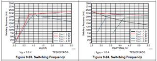
I have some questions about the switching frequency of TPS62825.
It is related to the question in the URL below.
e2e.ti.com/.../tps62825-change-of-switching-frequency-by-capacitor-at-vout

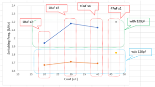
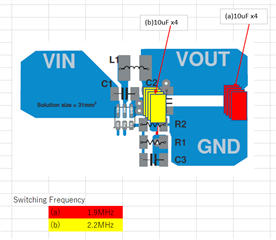
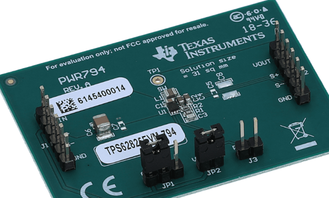
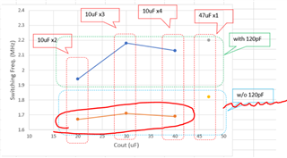
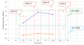
I measured the switching frequency of TPS62825 under various conditions, and the results are shown in the table below.


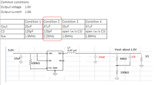
The purpose of the measurement is to find the condition at which TPS62825 operates at 2.2MHz for our application.
Fortunately, I was able to find the condition(which is condition 2), but the mechanism behind it is unknown.
Without understanding the mechanism, I can't determine whether condition 2 is robust against component variations, temperature, and other factors.(Whether frequency remains stable at 2.2MHz.)

Could you let me know the reason why the switching frequency increased in condition 2?
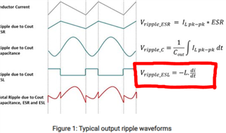
I read the previously introduced application note(slyt646.pdf) to try to understand the reason behind it, but I could not reach a conclusion.

Regards,
Kei

  • Hi Kei,

    Thank you for reaching out, I will get back to you later this week.

    Best regards,
    Louis

  • Hi Kei,

    The feedforward capacitor C3 is required, conditions 3 and 4 are therefore not valid.

    Regarding conditions 1 and 2, can you provide me the exact part numbers of Cout? Were the 22uF and the 47uF capacitors of the same case size? ESR and ESL can influence the DCS frequency.

    Best regards,
    Louis

  • Hi Louis,

    Thank you for your reply.

    I will get back to you in a few days.

    Best regards,
    Kei

  • Hi Louis,

    Actually, I used two 10uF to make 20uF.

    The exact part numbers are
    10uF: GRM155C80J106M (Murata)
    47uF: GRM188R60J476M (Murata)

    In terms of size, 10uF is smaller.

    For your reference, I am attaching additional evaluation results.

    Regards,
    Kei

  • Hi Kei,

    Louis is currently out of office. So allow me to respond.

    The switching frequency depends on the amount of output ripple. So a higher ESR/ESL of the output cap can cause a higher ripple that causes the hysteretic loop to respond faster and move to a higher switching frequency. That's probably why you see the 47uF with the highest ESR/ESL switch with the higher frequency. 

    For the cases where you have different number (2 to 4) of 10uF caps added, in theory the effective ESR/ESL should reduce. But the placement of these capacitors also matters and there could be higher board ESR/ESL for caps placed further away from the inductor. Could you check if the results change if you stack all the caps on top of each other and close to the inductor? 

    Best regards,

    Varun 

  • Hi Varun,

    Thank you for your reply.

    I checked the switching frequency under some conditions.
    The results are as follows.

    If capacitors were located after feedback point, the switching frequency was lower(1.9MHz).
    On the other hand, if capacitors were located before feedback point(close to the inductor), the frequency was higher(2.2MHz).
    Four caps were stacked on top of each other.

    Do you have any thought about what the reason might be?

    Regards,
    Kei

  • Hi Kei,

    Today is a holiday in Germany. Varun will get back to you by tomorrow.

    Thanks

    Yann

  • Hi Yann,

    Thank you for your response. I will be waiting for further reply.

    Regards,
    Kei

  • Hi Kei,

    In case (b), it could be that some of the magnetic field from the inductor is coupling onto the ESL of the output caps, causing a larger ESL voltage step and therefore an increased output ripple, which ultimately results in a higher switching frequency.

    Best regards,
    Louis

  • Hi Louis,

    Thank you for your explanation.

    Could you please provide a more detailed explanation regarding 'some of the magnetic field from the inductor is coupling onto the ESL of the output caps, causing a larger ESL voltage step and therefore an increased output ripple'? I would appreciate it if you could explain using some  figures or illustrations.

    Regards,
    Kei

  • Hi Kei,

    The following article is an interesting read in your case:
    Understanding and managing buck regulator output ripple - Power management - Technical articles - TI E2E support forums)

    To summarize, the ESL of the output capacitor will contribute a square-wave component to the total output ripple, see Figure 1 below.

    An unshielded inductor will produce a magnetic field around its leads, see Figure 3. If the output capacitor is put too close to the inductor, this field will couple onto its ESL, increasing the square wave component of the output ripple in Figure 1, and therefore the total output ripple itself.

    So it's a game of trade-offs: bringing the output capacitor closer to the inductor reduces PCB trace ESR and ESL, but increases magnetic coupling from the inductor.

    Best regards,
    Louis

  • Hi Louis,

    Thank for providing detailed explanation.

    I have a few questions.

    1.
    Regarding "If the output capacitor is put too close to the inductor, this field will couple onto its ESL, increasing the square wave component of the output ripple in Figure 1", it means when the coupling occurs, the current "i" in the equation increases, then Vripple_ESL increases, is my understanding correct?

    2.
    Is the data for the switching frequency of TPS62825 in its datasheet affected by the coupling?
    I believe the data was measured using TPS62825EVM, and since this board has the inductor and capacitor placed close together, it is likely that the data is affected by this coupling.


    3.
    TPS62825 tries to increase its switching frequency to reduce output ripple. However if the loop gain around the switching frequency(2MHz) is small, I believe the ripple around the frequency will not be controlled and therefore result in a rower switching frequency, is that correct?
    Regarding my previous post, when there was no Cff(120pF), which means gain at high frequency is low, the switching frequency was low(around 1.6MHz).

    4.
    Regarding the result below, when Cout is 20uF(10uF x2) with Cff, the switching frequency is lower compared to other conditions. For example, 30uF (10uF x3). Does this mean that 20uF (10uF x2) has a lower ESL compared to other conditions? Or is there less coupling in this case?

    Regards,
    Kei

  • Hi Kei,

    I will get back to you start of next week.

    Best regards,
    Louis

  • Hi Kei,

    I have answered your questions below.

    But first, I want to emphasize that if you want to operate your device at a fixed frequency of exactly 2.2MHz in all conditions, then our DCS control devices are not the right choice for you. There is always going to be some variation in frequency in DCS control. I recommend taking a look at for example the TPS628512 instead.


    1. The magnetic field of the inductor is dependent on the inductor current and should therefore produce a square voltage wave as well, which is then added on top of the one in Figure 1 through coupling.

    2. Most likely, yes.

    3.  I am not sure how the device works without Cff. DCS control devices use hysteresis based control loops, i.e. they need a ramp signal to compare against. In the DCS topology, this ramp signal is generated via the VOS (Vout sense) pin, see image below. Since the TPS62825 doesn't have a VOS pin, only a feedback pin, the feedforward capacitor Cff is required for proper coupling to FB to generate the correct ramp signal.
    4. If I'm not mistaken, those measurements were taken before you stacked the capacitors on top of each other, correct?

    Best regards,
    Louis

  • Hi Louis,

    Thank you for the detailed explanation.
    I understand DCS control devices are not suitable for fixed frequency.

    Regarding No.4, in this measurement, capacitors are stacked to achieve a parallel connection.

    Regards,
    Kei

  • Hi Kei,

    Then I'm not sure what's going on regarding the measurement in question 4. I'd have to check internally.

    Best regards,
    Louis