- Ask a related questionWhat is a related question?A related question is a question created from another question. When the related question is created, it will be automatically linked to the original question.
This thread has been locked.
If you have a related question, please click the "Ask a related question" button in the top right corner. The newly created question will be automatically linked to this question.
Hi Team,
Good day !!
Please help me with Power consuption of IC when we configure UCC14141-Q1 in below configurations:
1. UCC14141-Q1 with Two-wire system: if it is driver B-B MOSFETs with 10V and 1.3A Source/Sink
2. UCC14141-Q1 with Three-wire system: if it is driver B-B MOSFETs with 10V and 1.3A Source/Sink
(I am assuming 10Vx1.5A = 15W, it is huge and not sure about it)
Thanks in advance !!
Regards,
Manoj.
Hi,
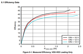
A quick estimation can be made to refer to the EVM test below (Using the UCC14141EVM-068 for Biasing Traction Inverter Gate Driver Device (Rev. A)).
So roughly the IC power consumption is around 55% to 65% of the IC average converter power output depending on the VIN.

Dear Hong Huang,
Thanks for clarifiacation, it is really helpful.
Could you please also help with TPSI3050-Q1 power consuption to drive the B-B MOSFET at max device driving capability (for all 3 modes)?
Thanks & Regards,
Manoj.
Hi,
TPSI3050-Q1 is supported by a different team. I have forwarded your request to that team. Please check and ask again if you do not see the reply within a day.
Hi Manoj,
Thank you for your question! To clarify, there are only two modes of operation for our device: two-wire mode and three-wire mode. Two-wire mode has lower power transfer whereas three-wire mode has higher power transfer and as a result higher switching speeds. But overall, both modes are application dependent. To better assist you, I have a couple questions about your application as the maximum power consumption can change depending on the way the device is implemented.
Thanks,
Sam
Hi Sam,
Good day ! PLease see the below ans:
MM: Driving B-B switches in AC Switch application
MM: It is for solid state driving
MM: STY145N65M5
Regards,
Manoj
Hello Manoj,
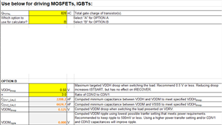
Thanks for your response. To provide you with the following information, I am using our Calculation Tool (SLVRBI9) available here. If you were to change part of your setup (e.g. select different MOSFETs), please refer to the Calculation Tool and input the changes to see the performance difference.
FET Qg = 414 nC
Would suggest setting CDIV1 = 2.2 uF and CDIV2 = 6.8 uF

MM: It is for solid state driving
For various power transfer settings in three-wire mode and two-wire mode, I've pasted the following tables below. It's unclear to me what switching speed you have provided so please refer to the power transfer tab in the Calculation Tool and determine the adequate R_PXFR selection based on your power consumption and switching frequency requirements.


Best regards,
Tilden Chen
Solid State Relays | Applications Engineer