This thread has been locked.

If you have a related question, please click the "Ask a related question" button in the top right corner. The newly created question will be automatically linked to this question.

TPS62085: The switching frequency is abnormal under different input & output conditions

Part Number: TPS62085

Hi team,

I am having issues measuring over the switching frequency:
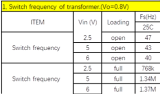
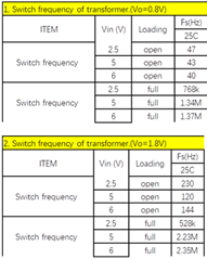
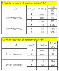
Their test results:

I can understand that under light load, the fsw is reduced to save power.

I have also read the following application note:

Understanding frequency variation in the DCS-Control(TM) topology

But below is what confuse me:

1. According to the application note, the switching frequency deviates under high duty cycle and low duty cycle. My understanding is that fsw deviates more away from standard value (2.4 MHz) as the duty cycle increase or decrease. But from customer's test results, the fsw is even lower at low duty cycle (see the form of Vo=1.8V). 

2. TPS62085 supports 100% duty cycle operation according to the datasheet. Why is there still a minimum off-time? And what is the minimum off-time of TPS62085?

3. What is the specific "moderate" duty cycle range in the application note?

Thanks,

Frank

  • Hi Frank,

    1. The switching frequency should be close to the target for medium duty cycles (50%). For both high and low duty cycles, the switching frequency will be below target due to min off and on times. For 1.8V output, the frequency should be close to 2.4MHz at 3.6 VIN

    2. The minimum off time doesn't affect 100% mode operation. In 100% mode operation, there is no low side switching phase and hence the minimum off time has no influence. I couldn't find a min off time value in the characterization data for this device. I believe the minimum off time in this device is due to propagation delays of internal signals and a blanking time required to prevent wrong operation due to noise during the switching transition. 

    3. In figure 2a of the App note, the moderate duty cycle range seems to be from 9V to ~13V for 5V output and 2.5MHz switching. I think the range can vary for different DCS devices, depending on the ON times and propagation delays.

    Best regards,

    Varun

  • Hi Varun,

    Thanks for the reply. I have deleted the customer information since I notice that this thread is in public forum.

    I think I haven't described my first question clearly.

    What confuses me is that, if the switching frequency under high/low duty cycle is truly influenced by the minimum on/off time, the switching frequency should have a "trend" to deviate more from the specified frequency (2.4 MHz for TPS62085), as the duty cycle deviates from "moderate" to "high" or "low".

    But this is not the case for Vout=0.8V. As you can see from the test results, at 2.5V Vin (D~30%), the fsw is 768k. And at 6V Vin (D~13%), the fsw is 1.37M, which is closer to 2.4 MHz than 768k.

    How can we explain such a phenomenon?

    Thanks

    Frank

  • Hi Frank,

    That's a good point.

    One additional information is that output ripple also has an effect on the switching frequency. Since this is a hysteretic mode converter, the frequency also has a dependence on the ESL, ESR of the output caps. A larger output ripple (ESL step) on the output can trigger the control loop to switch faster. I think that is probably what is happening with the very high VIN. The ESL voltage step on the output cap, depends on the magnitude of the inductor current ripple, which is high for higher VINs. 

    Best regards,

    Varun