This thread has been locked.

If you have a related question, please click the "
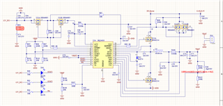
Ask a related question" button in the top right corner. The newly created question will be automatically linked to this question.

BQ24610: BQ24610输出异常

Part Number: BQ24610

I made a power charge and discharge management scheme with BQ24610 chip. After the circuit board was welded, the power output was abnormal: the LED of PG pin was abnormally blinking, and the BAT output was abnormal (at this time, the output was about 1.17V) (Note: My power input was 15V, and the battery voltage was designed to be 12.6V). The power circuit design is shown in the following figure:

  • Hi Hao, 

    Thank you for reaching out!

    Could you please provide the capacitor values used in the schematic? I am unable to tell the capacitance of C72, C74, and C75 for instance. 

    Could you also provide a scope capture of VCC, VREF, PG, and REGN signals? (similar to figure 1 in section 8.6 of the datasheet)

    Best Regards, 

    Aya Khedr

  • The c72 uses 100NF and the C74C75 uses 10uf. Now I don't have an oscilloscope to help review the picture to see the principle is there a problem? In addition, the upper PG of the board is connected with an LED light, which keeps flashing when it is powered on.

  • Hi Hao, 

    In the schematic, the input adapter voltage is 12V but in your description here you said that you input is 15V, so I would like to verify that it is 15V, correct?

    Also, please see the attachment which contains charger calculations for important parameters and verify that the values are aligned with what your design is trying to achieve. One thing to note is that Cttc (C80) seems to be very small (see electrical characteristics table below).  

    BQ24610_Hao.xlsx

    Best Regards, 

    Aya Khedr 

  • The power supply is 15V, and the battery output voltage is 12.6V. I designed it to be compatible with two voltage outputs: 12.6V and 8.4V. For 12V power supply, you need to modify the rear R104 to adjust the battery output voltage to 8.4V. I am checking my welding problem. Thank you for your help in reviewing the drawing.

  • Hi Hao, 

    Thank you for the clarification. 

    The capacitor on TTC pin is correlated to the fast charge safety timer. The minimum time is 1h which means that the minimum capacitance on that pin is at about 11nF (estimated). 

    Feel free to reach out if you have additional questions/concerns. 

    Best Regards, 

    Aya Khedr 

  • I will modify it and try again. Thank you for your help and support these days

  • Hi Hao, 

    No problem!