This thread has been locked.

If you have a related question, please click the "Ask a related question" button in the top right corner. The newly created question will be automatically linked to this question.

USB-PD-CHG-EVM-01: Configuration GUI issue for TPS25750 & BQ25798

Part Number: USB-PD-CHG-EVM-01
Other Parts Discussed in Thread: BQ25798, TPS25750EVM, TPS25750, BQ25792, BQ25731

Hello,

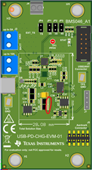
I just received the EVM and followed the instructions verbatim and cannot get the GUI output to generate >5V output.  My issue is similar to that found in another thread and it certainly would be nice if the GUI was updated to actually generate a file that works.

https://e2e.ti.com/support/power-management-group/power-management/f/power-management-forum/1278134/usb-pd-chg-evm-01-tps25750-not-sourcing-as-expected

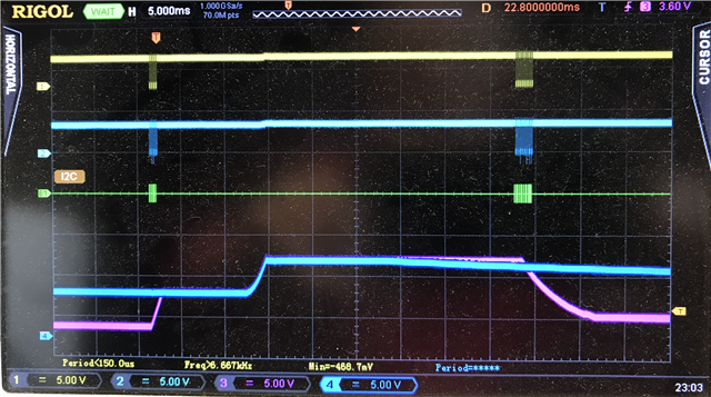
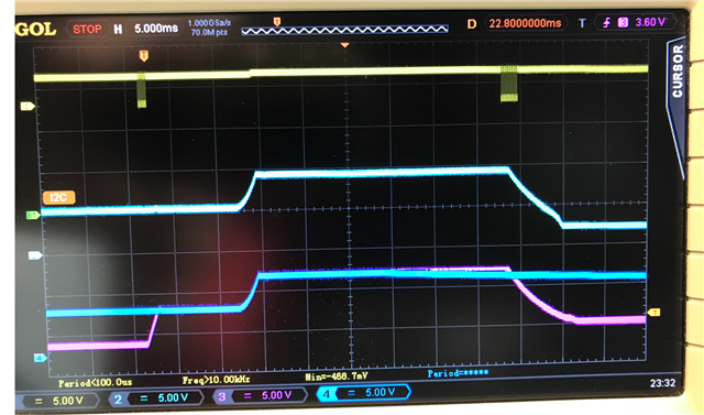
I see the very same behaviour as Nate did in that thread.

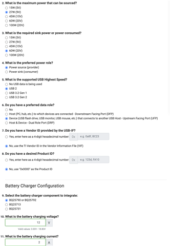
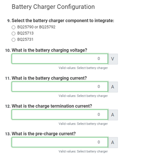
What I have gotten to work is a single PDO @5V, but any higher voltage output that makes use of the BQ25798 fails.  Why does the GUI not have the BQ25798 listed as an option as shown in the video provided by TI?

I can provide configuration file so that someone could generate a working binary file.

Thanks,

Richard

  • @Alex Lui sent me a message in the other thread:

    "We unfortunately do not support binary file generation for USB PD CHG EVM projects as the GUI is working for that application.  The GUI can be used to generate the binary file"

    I am a little confused, is the GUI not able to generate a binary file for my EVM?

    Richard

  • Hi Richard,

    I'm curious, does your PP5V line increase to PPHV for any contract negotiation attempt above 5V? Do you have an oscilloscope to measure this?

    This is where I measured PP5V:

    Cheers,

    Nate

  • Hi Richard,

    To clarify my statement:

    The GUI can generate the binary file but you will need to do this yourself. We will not generate the binary for you as the GUI is working for CHG EVM setups. Please try the project configurations and binary file in the other thread. Those are confirmed to work for CHG EVM.

    Best,

    Alex

  • Hi Nate,

    I did not measure the PP5V line as that supply should remain at 5V as it is connected to a one way switch within the 25750.

    During my debugging yesterday, I used my scope and confirmed that the output of the BQ25798 does indeed increase to 9V when PDO2 is set for 9V.  I measured on the PPHV (red) scope test point.  The 25750 does request this voltage from the BQ, but then a few 100's mS later it has some more i2C communications and the PPHV line drops.  

    On the USB side during this time, there is never a confirmation of PS_RDY when 9V is present.  

    The whole cycle repeats forever.

  • I would like to do more than function as a battery charger.  I would like to:

    Any chance the EVM can do that? 

    What I have been able to get the EVM to do successfully is output 5V when #2 is set to 15W (5V).

    Thanks

  • Hi Richard,

    With the project file I sent in the other thread, you should be able to output 45W from the USB PD CHG EVM when a battery or power supply is connected to the battery pins.

    In terms of data, our EVMs are designed to be proof of concepts for data connections, but do not carry USB data. We do not have any data muxes or usb hubs on the EVM for data communication, but you can see the GPIOs toggling correctly to configure data mux and redriver parts, as well as I2C data transmitting correctly to configure retimers. You should also be able to see the PD advertise itself correctly as DFP/UFP/DRP, USB2, USB3, TBT, and DP supporting, depending on user configuration. You can use a TPS25750EVM to accomplish this.

    The USB PD CHG EVM is designed to demonstrate battery charging or PD sourcing scenarios only. The CHG EVM does not have breakouts for GPIOs where signals can be probed. You will still be able to see data advertisement as DFP/UFP/DRP and USB2, USB3, TBT, DP through PD messages and PD registers.

    I would suggest using the USB PD CHG EVM to test battery charging and TPS25750 EVM to test USB data support. Please let me know if you have further questions.

    Best,

    Alex

  • Hi Alex,

    I can get by with the EVM to manage the VBUS and CC lines, and inject just those into my prototype that I already have.  So the USB data lines are covered already.   

    The bin from the other thread works for me as follows:

    I have successfully used the EVM as a sink to charge my 3S battery. 

    With the EVM as the source and the sink requests object position 1 contract for 5V it functions correctly.

    With the EVM as the source and the sink requests the object position 2 contract for 9V the PS_RDY message never gets sent by the TPS25750 over the CC lines to the sink.  The messaging leading up to the point where the PS_RDY message should happen all look good.  Ie. the sink is requesting the object position 2, CRCs are good, and the SRC is accepting the request.

    Is there a way to use the TPS25750 as a source only with 5V connected to PP5V and a fixed 9V connected to PPHV and not use the BQ at all?  Thus removing the need for i2c communications with the charger and all its complexity.  I only need the two source capabilities for my application.  

    Thanks

  • Hi Richard,

    I assume you are referring to the USB PD CHG EVM binary I provided.

    To debug the issue further, could you provide I2C logs of the I2Cm lines which carry traffic from the TPS25750 to the BQ part for configuration and the PD logs indicating PS_RDY not sent? Let me know if you need help finding these signals on the board.

    You can use the TPS25750 as a source only with 5V connected to PP5V and a fixed 9V connected to PPHV without a BQ part, provided you are not going to use a battery. However, this is not possible without rework on the USB PD CHG EVM or TPS25750 EVM given the board designs. 
    If you only wish to test 5V and 9V capabilities of the TPS25750, I recommend using the TPS25750EVM with the TPS25750EVM_SourceSink binary file I provided in the other thread.

    Best,

    Alex

  • Hi Nate,

    I created a new GUI config with two PDOs, the first for 5V and the second for 9V.  Scope Channel 3 is the PPHV, and Channel 4 is the PP5V.  It can be seen that PP5V goes to the 9V just like PPHV.  Channel 1 and 2 show the I2C communication to the BQ25798 during this event. 


    My PP5V measurement was taken off the output L2.  I am surprised as you were to see this happen!  Good thing 20V was not requested.  It looks to me like the PP5V FET is not shut off.

    Nate, are you able to get 9V output from the bin that Alex provided to you?  As it only ever provided 5V output for me.

    Regards,

    Richard

  • Captured the same as above but added the VBUS measurement on channel 2.  It is reaching 9V which to me confirms that the PP5V switch is not turning off when higher than 5V output is requested.

    PP5V reaching higher than 5V would certainly strain capacitor C26.

  • Of interest is how PPHV behaves with two (5V and 9V) power roles being defined in the GUI. 

    When the sink requests the 5V PDO, I see the PPHV go to 9V as commanded by the TPS25750.  But both VBUS and PP5V remain at 5V:

    I have zoomed in to show the i2c comm to address 0x0B data 0x026C, which instructs 9V to be output from BQ.  Scope trace 3 (magenta) goes to 9V not much later.


  • Hi Richard,

    What you are seeing is very similar to what Nate was seeing in the other thread. PP5V should not be ramping up with PPHV beyond 5V. 

    From your scope captures, the PP5V switch is opening for the 9V contract because when PPHV drops, VBUS drops with it. If PP5V switch was closed still, VBUS would not drop. In our firmware, PPHV closes before PP5V opens in the TPS25750 when transitioning from 5V to 9V contracts. RCP may have failed causing PP5V to see the 9V. Once we open the PP5V switch, we have no way of discharging the 9V on PP5V causing OVP.

    A couple things to note:

    • The DC/DC 5V converter on the CHG EVM is hardwired using a resistor divider to output 5V, so it must be a short between PPHV and PP5V (possibly through the PP5V switch not disabling) that is the cause.
    • The BQ25792 part will be programmed to output 9V when the 5V contract is active. This 9V is not seen on VBUS because the PPHV switch should be open for the 5V contract.
    • The BQ part on the CHG EVM should be a BQ25792, not a BQ25798. I know the BMS-BCP team is planning to release a new version with the BQ25798 but I do not believe that is available yet. The guides and documents have been updated on ti.com in preparation for the new release. However, the configuration of the BQ25798 part should be the same as the BQ25792 so there should be no differences in the projects or binaries.

    Is the 9V on PP5V during a 9V active PD contract also seen using the binary I provided (I believe you said PPHV from the BQ part does go to 9V even when PS_RDY is not sent)?

    Best,

    Alex

  • Richard, Could remove Caps C27 and C28 and try? the ripple may increase so you can try C27 first and then both C27 and C28.

  • Hi Richard,

    Thank you for your well laid out findings.

    With a 10.5V power supply attached to J2 of the CHG-EVM and the profile provided by Alex from the other chat I have collected the following data:

    Green: BQ25792 SDA Line

    Yellow: PPHV

    Red: PP5V

    PD Data: BQ25792_CHG_EVM_Source_Sink.zip 


    ^ Snipit of PD data.


    Is the 9V on PP5V during a 9V active PD contract also seen using the binary I provided (I believe you said PPHV from the BQ part does go to 9V even when PS_RDY is not sent)?
    Nate, are you able to get 9V output from the bin that Alex provided to you?  As it only ever provided 5V output for me.

    I cannot and have never gotten a 9V profile from the CHG-EVM even with the provided binaries. The PS_RDY message is never sent for >9V profiles. I have gotten the TPS25750EVM to provide all standard sourcing profiles in a DRP configuration with the provided BQ25731 binaries however.


    Richard, Could remove Caps C27 and C28 and try? the ripple may increase so you can try C27 first and then both C27 and C28.

    Perhaps I am not understanding fully how this system works, but what would removing these capacitors achieve? With the device off, I have probed the resistance between PP5V, PPHV, and GND. There is no short.

    It seems odd to me that both Richard and I's CHG-EVM boards are both not working the same way, and your board is working Alex. The exact chip I have on my CHG-EVM is: 25750D TI 11F S32S G4

  • From your scope captures, the PP5V switch is opening for the 9V contract because when PPHV drops, VBUS drops with it. If PP5V switch was closed still, VBUS would not drop. In our firmware, PPHV closes before PP5V opens in the TPS25750 when transitioning from 5V to 9V contracts. RCP may have failed causing PP5V to see the 9V. Once we open the PP5V switch, we have no way of discharging the 9V on PP5V causing OVP.

    After re-reading Alex's post, I think I understand why removing these caps might fix the problem if it is indeed intentional that PP5V opens after PPHV closes. (Open = stopping current, Closed = Allowing current).

    Removing cap C27 and C28 makes the PP5V bus drop quicker after its connection is opened, but this doesn't change the overall behavior. Nor does it explain why Alex has a working CHG-EVM while Richard and I do not.

    Nate

  • It made no sense to me why removing a couple of ceramic capacitors would prevent the PP5V from being driven by PPHV.  The drive capability of the PPHV supply is 3A so will easily back drive a couple of filter capacitors.  The real solution is to ensure the PP5V switch is open when PPHV switch is closed and has valid 5V.  I have marked up your diagram to show where the PP5V switch should open.  With the switch open there is never a chance of back driving PP5V to any of the higher PPHV selections of even 20V!  


    Like you, I have not gotten Alex's binary file to provide a valid VBUS output of greater than five volts.  The first issue that needs to be solved is to prevent PP5V from exceeding 5V.  The maximum rating for PP5V from data sheet is 6V BTW.

    The exact chip I have on my CHG-EVM is: 25750D TI 11F S32S G4.  My board serial number is 7904700013 and was purchased from Digikey. 

    Alex, are you able to purchase one of the EVMs with similar serial number as mine and try out your binary on it?  You being able to debug on the same revision board would certainly speed up the process. I suspect there is an issue with the online tool for creating binaries that is preventing successful operation of the new boards.  

    How can we wrap this up quickly as I need to make a decision on the direction of my design?

    Thanks for your help,

    Richard

  • Hi Alex,

    I have tried both files that you linked in the other thread as requested.  Neither one negotiates a 9V contract successfully with my sink.  But there is a difference in the behaviour between the two binaries.

    TPS27250_EVM_Source_sink.bin

    - I see four PDO sources capabilities being broadcast out USB CC

    - My Sink requests the 9V source

    - Only a 5V VBUS output is generated

    - continuously cycles

    BQ25792_CHG_EVM_Source_Sink.bin

    - I see four PDO sources capabilities being broadcast out USB CC

    - My Sink requests the 9V source

    - A 9V VBUS output is generated but never locked (ie PS_RDY never happens) in by the EVM as it has PP5V going to 9V and resetting.

    - Continuously cycles 

    As an FYI, I am using the CH431A programmer to upload the binary files to the EEPROM.

    Thanks,

    Richard

  • Ah, I missed the serial number on the back.

    As stated before, the exact chip I have on my CHG-EVM is: 25750D TI 11F S32S G4

    And the board serial number is: 7904700030 also purchased from digikey.

    Nate

  • Hi Richard,

    A lot of updates here so let me summarize them:

    1. We are seeing multiple cases in customer EVMs where PP5V path on TPS25750 is ramping to PPHV voltage when PD switches to PPHV power path.
    2. You see that with the TPS25750_EVM_Source_Sink.bin file, the TPS25750 sends the proper source capabilities to the far end but only 5V is presented on VBUS. Are you using the CHG EVM to test this or a TPS25750EVM? The CHG EVM has a different BQ part (BQ25731 vs BQ25792/8) that will not be configured correctly with the TPS25750 EVM binary.
    3. You see that with the BQ25792_CHG_EVM_Source_Sink.bin file, a 9V VBUS is generated but PS_RDY is not sent and PP5V ramps to PPHV voltage during power path switch.
    4. Nate tested the CHG EVM behavior with C27 and C28 caps removed, but PP5V voltage was still ramping with PPHV.

    A couple comments from me:

    1. The reason you see the CHG EVM cycling is because the TPS25750 is seeing OVP on the PP5V path when it ramps to 9V. It will not continue to operate under these conditions.
    2. It is correct behavior for PPHV switch to enable before PP5V switch is disabled. The TPS25750 requires power from PP5V to control the gate drivers for PPHV. We use RCP to prevent PPHV voltage from being seen on PP5V when the "make then break" power path switch operation occurs.
    3. The reason we proposed removing some capacitance (C27 and C28) was that high capacitance on PP5V could cause RCP to fail. Since the TPS25750 relies on RCP to prevent PPHV voltage from being seen on PP5V during power path switches, a failure of RCP could have been the issue. High capacitance would mean slower charging of the caps, which will cause the TPS25750 to see RCP later, potentially too late. Once the PP5V switch opens with 9V already seen, we do not have a way of quickly discharging it, so OVP would be triggered.

    I discussed further with my team and it seems like the TPS25750 is configuring the BQ25792 to go to 5V before 9V in your scope capture, this is not correct. The voltage from the BQ part should go straight to 9V. This was introduced to prevent the RCP issue, but looks like this workaround is not in the json project being used.

    Can you run the test one more time and let me know if PP5V ramps to 9V with the exact attached json project? I want to confirm the issue is seen with this json project so I can investigate and provide a working project. I will also run some more tests on my side on additional CHG EVMs to see if it can be reproduced. We are looking into this actively and will provide an update in the next 1-2 days.

    {"questionnaire":{"version":"7.0.4.6","answers":[0,2,3,0,0,null,1,null,1,null,0,8.4,2,0.04,0.04],"options":{},"configID":"0000","vendorID":"0000"},"configuration":{"data":{"selected_ace":[{"register":6,"data":[170,170,0,0,187,187,0,0]},{"register":22,"data":[10,48,48,77,0,0,0,0,0,0,3]},{"register":23,"data":[8,4,0,2,0,0,0,0,0,0,0]},{"register":31,"data":[0,0,0,0,0,0,0,0,0,0,0,0,0,0,0,0,0,0,0,0,0,0,0,0]},{"register":32,"data":[0,0]},{"register":35,"data":[0,224,1,0]},{"register":39,"data":[5,9,20,0,28,7,0,0,80,81]},{"register":40,"data":[2,8,47,0]},{"register":41,"data":[210,80,201,0]},{"register":43,"data":[0,2,0,0,2,0,0,0]},{"register":50,"data":[3,168,42,44,145,1,38,44,209,2,0,44,177,4,0,244,65,6,0,0,0,0,0,0,0,0,0,0,0,0,0]},{"register":51,"data":[4,44,145,1,16,44,209,2,0,44,177,4,0,44,65,6,0,69,65,6,0,0,0,0,0,0,0,0,0]},{"register":55,"data":[59,192,18,100,144,145,1,0,0,0,0,0,0,0,0,0]},{"register":66,"data":[10,0,0]},{"register":67,"data":[0,0,0,0,0,0,0,0,0,0,0,0,0,0,0,0,0,0,0,0,0,0,0,0,0,0,0,0]},{"register":71,"data":[6,81,4,64,149,81,4,0,0,5,9,0,0,0,0,0,104,0,0,0,0,0,0,0,71]},{"register":74,"data":[0,0,0,0,0,0,0,0,0,0,0,0,0,0,0,0,0,0,0,0,0,0,0,0,0,0,0,0,0,0,0,0,0,0,0,0,0,0,0,0,0,0,0,0,0,0,0,0,0,0,0,0,0,0,0,0,0,0,0,0,0,0,0]},{"register":75,"data":[0,0,0,0]},{"register":81,"data":[0,6,0,0,0,0]},{"register":82,"data":[0,128,0,0,0,0,0]},{"register":86,"data":[63,128]},{"register":92,"data":[48,0,0,0,0,0,0,0,0,16,0,0,0,0,0,0,48,0,0,0,0,0,0,0,0,12,0,0,0,0,0,0,0,0,0,0,0,0,0,0,0,0,0,0,0,0,0,0,0]},{"register":93,"data":[0,0,0,0]},{"register":98,"data":[0,0,1,46,0,0,0,0]},{"register":100,"data":[107,0,0,0,0,0,0,0,0,0,0]},{"register":108,"data":[0,0,0,0,0,0,0,0,0,0,0,0,0,0,0,0,0,0,0,0,0,0,0,0,0,0,0,0,0,0,0,0,0,0,0,0,0,0,0,0,0,0,0,0,0,0,0,0,0,0,0,0,0,0,0,0,0,0,0,0]},{"register":111,"data":[0,0,0,0,0]},{"register":112,"data":[0]},{"register":115,"data":[0,0,0,0,0,0,0,0,0,0,0,0,0,0,0,0,0,0,0,0,0,0]},{"register":117,"data":[0,0,0,0]},{"register":119,"data":[0,0,0,0,0,0,0,0,0,0,0,0,0,127]},{"register":121,"data":[0,0,0,0,0,0]},{"register":123,"data":[0,2,255,255,0,0,0,0,0,0,0,0,0,0,0,0]},{"register":125,"data":[0,0,0,0,0,0,0,0,0,0,0,0,0,0,0,0,0,0,0,0,0,0,0,0,0,0,0,0,0,0,0,0,0,0,0,0]},{"register":126,"data":[0,0,0,0,0,0,0,0,0,0,0]}],"bin_table":[{"rights":0,"register":0,"data":[],"offset":0},{"rights":0,"register":1,"data":[35,2,0,16,128],"offset":0},{"rights":0,"register":2,"data":[35,2,0,20,28],"offset":0},{"rights":0,"register":3,"data":[35,2,0,17,0],"offset":0},{"rights":0,"register":4,"data":[35,2,0,18,0],"offset":0},{"rights":0,"register":5,"data":[35,2,0,8,1],"offset":0},{"rights":0,"register":6,"data":[35,2,0,9,1],"offset":0},{"rights":0,"register":7,"data":[35,3,0,1,3,72],"offset":0},{"rights":0,"register":8,"data":[35,3,0,3,0,200],"offset":0},{"rights":0,"register":9,"data":[37,2,0,16,128],"offset":0},{"rights":0,"register":10,"data":[37,2,0,20,28],"offset":0},{"rights":0,"register":11,"data":[37,2,0,17,0],"offset":0},{"rights":0,"register":12,"data":[37,2,0,18,0],"offset":0},{"rights":0,"register":13,"data":[37,2,0,8,1],"offset":0},{"rights":0,"register":14,"data":[37,2,0,9,1],"offset":0},{"rights":0,"register":15,"data":[37,3,0,1,3,72],"offset":0},{"rights":0,"register":16,"data":[37,3,0,3,0,200],"offset":0},{"rights":0,"register":17,"data":[36,2,0,16,128],"offset":0},{"rights":0,"register":18,"data":[36,2,0,20,28],"offset":0},{"rights":0,"register":19,"data":[36,2,0,17,0],"offset":0},{"rights":0,"register":20,"data":[36,2,0,18,0],"offset":0},{"rights":0,"register":21,"data":[36,2,0,8,1],"offset":0},{"rights":0,"register":22,"data":[36,2,0,9,1],"offset":0},{"rights":0,"register":23,"data":[36,3,0,1,3,72],"offset":0},{"rights":0,"register":24,"data":[36,3,0,3,0,200],"offset":0},{"rights":0,"register":25,"data":[1,2,0,22,192],"offset":0},{"rights":0,"register":26,"data":[1,3,0,1,3,72],"offset":0},{"rights":0,"register":27,"data":[1,3,0,3,0,200],"offset":0},{"rights":0,"register":28,"data":[2,2,0,22,192],"offset":0},{"rights":0,"register":29,"data":[2,3,0,1,3,72],"offset":0},{"rights":0,"register":30,"data":[2,3,0,3,0,200],"offset":0},{"rights":0,"register":31,"data":[38,2,0,20,28],"offset":0},{"rights":0,"register":32,"data":[38,2,0,13,83],"offset":0},{"rights":0,"register":33,"data":[38,3,0,11,2,108],"offset":0},{"rights":0,"register":34,"data":[38,2,0,18,64],"offset":0},{"rights":0,"register":35,"data":[39,2,0,20,28],"offset":0},{"rights":0,"register":36,"data":[39,2,0,13,75],"offset":0},{"rights":0,"register":37,"data":[39,3,0,11,2,108],"offset":0},{"rights":0,"register":38,"data":[39,2,0,18,64],"offset":0},{"rights":0,"register":39,"data":[40,2,0,20,28],"offset":0},{"rights":0,"register":40,"data":[40,2,0,13,75],"offset":0},{"rights":0,"register":41,"data":[40,3,0,11,4,196],"offset":0},{"rights":0,"register":42,"data":[40,2,0,18,64],"offset":0},{"rights":0,"register":43,"data":[41,2,0,20,28],"offset":0},{"rights":0,"register":44,"data":[41,2,0,13,125],"offset":0},{"rights":0,"register":45,"data":[41,3,0,11,6,184],"offset":0},{"rights":0,"register":46,"data":[41,2,0,18,64],"offset":0},{"rights":0,"register":47,"data":[],"offset":0},{"rights":0,"register":48,"data":[],"offset":0},{"rights":0,"register":49,"data":[],"offset":0}]}}}

    Thanks for being patient with this. This is a cross-team debug effort for us.

    Best,

    Alex

  • Hi Alex,

    As a PD sink, I am using two devices.  For a simple load the Infineon Technologies CY4534 EZ-PP BCR PLUS Evaluation Kit is being used.  It allows a PDO to be selected and tested.  For a more complicated device I am using the Android powered 360 deg camera that will be used in the end product. 

    From your comments, I would expect that RCP is not relied upon for actual switch control, RCP should be the backup just in case the PP5V is left on.  PP5V should be turned off as soon as PPHV has the BQ generated 5V flowing to VBUS.  Then the BQ should be programmed to increase its output to the selected PDO.

    OK, I have tested your latest json.

    If I select PDO1 to provide 5V output, VBUS is at 5V and PS_RDY is output and all is stable.  Of interest is the fact that PPHV has 9V generated by the BQ during this state.

    If I select PDO2 to provide 9V output, the following is see as before with the repeating cycle:


    If I select PDO3 to provide 15V output, the repeated cycle is done again:

    Note, my board does not have the PP5V capacitors removed.

    Regards,

    Richard

  • Hi Alex,

    To be thorough, I have my CHG-EVM in the following configuration:

    • JP1 populated, JP2 not populated, JP3 not populated
    • J2 connected to a 8.4V bench supply ( The charge voltage you defined in the "USB_PD_CHG_EVM_Test.json" config)
    • C27 and C28 are still removed on my CHG-EVM.

    To flash the configuration to the EEPROM I am using an in house developed script to emulate the Tiva chip on the TPS25750EVM. This script also implements the flash verification step that the customization tool performs post flash, and has also been tested extensively. All that to say, I am directly flashing from the "TPS25750 Application Customization Tool" v7.0.4.6.

    When loading and flashing the provided "USB_PD_CHG_EVM_Test.json" into the customization tool I followed the below steps:

    • Open a fresh instance of the customization tool as an administrator.
    • Click "New Configuration" to ensure there weren't any settings saved from my previous session.
    • Click "Browse" right below the "Export Settings" button and navigated to and selected the downloaded "USB_PD_CHG_EVM_Test.json" file.
    • Clicked "Flash To Device From Current Configuration" at which point I monitor the I2C traffic on the bus with a TotalPhase Beagle and see the following:
      • The EEPROM is erased with 0xFF across all of its registers.
      • The EEPROM is flashed with the generated data.
      • The EEPROM data is verified by reading the registers back to the application customization tool.
    • I then power cycle the device by turning the bench supply off and on again. I also verify the power cycle by monitoring the I2C traffic between the EEPROM, TPS25750, and BQ25792.
    • Then I plug in a 9V sink device into the USB C port.

    The behavior of this configuration is the same as before. RED = PP5V, YELLOW = PPHV, GREEN = I2Cm_SDA.

    Hope this helps,

    Nate

  • Hi Richard, Nate,

    I am working on a fix for this issue. It has to do with how the TPS25750 is configuring the BQ25792 part when certain PD source contracts are negotiated. I am making the fix and testing it. I will update you when I have it working soon.

    Best,

    Alex

  • Hi Alex,

    Thank you very much for the update.

    An other option that I would like to investigate further has the following power diagram for the TSP25750:

    Do you know if I can configure this through the online GUI and generate a bin that will work?

    Regards,

    Richard

  • Hi Richard,

    Yes, your desired behavior and setup is possible.

    You can make the following changes in the GUI configuration:

    1.) Leave the config as below:

    2.) Do not select a battery charger component and set charger voltage/current to 0.

    3.) Change the GUI to advanced configuration. Modify the TX Sink Capabilities register to have 0 sink PDOs.

    I am not 100% positive of the DR swap initiation. If you find the PD does not do the DR swap to UFP, I can provide a json project that does.

    If you wish to test this, I recommend using the TPS25750 EVM instead of the USB PD CHG EVM. Using the TPS25750 EVM, you can hook up the 9V supply to PPHV using any of pins 1-4 of the J3 header. You can also test this with the USB PD CHG EVM by hooking up the 9V supply to the PPHV test point and flashing the binary when the board is powered using the type C connector only.

    Best,

    Alex

  • Hi Alex,

    I followed your directions for the source only instructions as you provided.  The Generate Full Flash Binary button never gets enabled and thus I cannot generate a binary file.  The GUI must be doing a check on the EVM selection in step #1 above;  as soon as I check the one to the right of it I am allowed to generate a binary file.  If you can provide a json that will allow me to generate a binary that would be great.

    Thanks,

    Richard 

  • Hi Richard,

    It seems like this is a GUI limitation. I can provide a binary with your settings. Do you already have a JSON file you were trying to use to generate the binary? I am also still working on making a fix for CHG EVM sourcing issue. Progress has been made and it can source >5V now, but the PP5V ramping issue is not fully resolved. I will update you again when I have the fix.

    Best,

    Alex

  • Hi Alex,

    Thanks for the feedback on the initial >5V issue.  I am sure it is taking quite a bit of effort on a number of fronts to get all the pieces working together.

    The JSON file for the fixed (no BQ connected) 5V in and PPHV = 9V with DR_SWAP as shown in my diagram has contents:

    {"questionnaire":{"version":"7.0.4.7","answers":[0,1,0,0,1,2,1,null,1,null,null,0,0,0,0],"options":{},"configID":"0000","vendorID":"0000"},"configuration":{"data":{"selected_ace":[{"register":6,"data":[0,0,0,0,0,0,0,0]},{"register":22,"data":[10,48,48,77,0,0,0,0,0,0,3]},{"register":50,"data":[2,168,42,44,145,1,38,44,209,2,0,44,177,4,0,44,65,6,0,0,0,0,0,0,0,0,0,0,0,0,0]},{"register":51,"data":[0,44,145,1,16,44,209,2,0,44,177,4,0,244,65,6,0,69,65,6,0,0,0,0,0,0,0,0,0]},{"register":92,"data":[48,0,0,0,0,0,0,0,0,16,0,0,0,0,0,0,48,0,0,0,0,0,0,0,0,12,0,0,0,0,0,0,0,0,0,0,0,0,0,0,0,0,0,0,0,0,0,0,0]},{"register":117,"data":[0,0,0,0]}]}}}

    Sorry I did not figure out how to attach the actual json file to this post so just inserted the code.  Looking forward to testing the binary on my board.

    Best regards,

    Richard

  • Hi Richard,

    I will try to get you the binary file tomorrow. The json text should be ok.

    Best,

    Alex

  • Hi Richard,

    Please see the full flash binary attached.

    https://e2e.ti.com/cfs-file/__key/communityserver-discussions-components-files/196/TPS25750_5F00_DualPath_5F00_SourceOnly_5F00_UFPPreferred_5F00_NoBQ.bin

    Config:

    PP5V and PPHV Source Only

    5V/3A Source PDO on PP5V, 9V/2A Source PDO on PPHV

    DRP State Machine w Auto Initiation of DR Swap to UFP

    USB2 Support Only

    No BQ Part Needed

    Best,

    Alex

  • Hi Alex,

    Thanks for sending over the "TPS25750_DualPath_SourceOnly_UFPPreferred_NoBQ.bin"

    I have tested it and found that it still is looking for the BQ25792 to be on the i2c bus.  Besides that I can see that that it is presenting correctly to the USB Type C port.  With the DR swap support as expected.  For full functionality I still need to write some microcontroller code to make the board more functional.

    Currently I have received my own PCB assembly with the BQ25792 and TPS25750 designed in.  My preference for this PCBA is still to use the TPS25750 to manage the BQ25792 output voltage generation for VBUS, and would like to use the GUI to generate the appropriate binary. Would you be able to provide an update as to how you are making out on the GUI fix and release?

    Thanks,

    Richard

  • Hi Richard,

    I am not sure why the PD is still looking for the BQ part as all I2C events should have been disabled. However, it should not be an issue.

    For the fix, we are still working on this and are between a firmware and GUI fix. We will update you next week on progress.

    Best,

    Alex