This thread has been locked.

If you have a related question, please click the "Ask a related question" button in the top right corner. The newly created question will be automatically linked to this question.

USB-PD-CHG-EVM-01: TPS25750 not sourcing as expected.

Part Number: USB-PD-CHG-EVM-01
Other Parts Discussed in Thread: TPS25750, , BQ25792, TPS54531, BQ25731, BQ25756, TPS25750EVM, BQ25798

Hi,

I am running into some roadblocks with the TPS25750 chip and want to confirm the behavior I am seeing is expected.

Our goal with this chip is to create a power bank device that only interfaces through USB C with a preferred power role of source, and minimum power profiles in both directions of 60W. Ie it must support all standard profiles between 5V/3A to 20V/3A (Ideally 100W as well)

  1. I have tried loading many configurations onto the USB-PD-CHG-EVM-01 with the following findings: Sinking profiles all the way up to 100W work, and the only sourcing profile that this chip is capable of is 5V/3A. Is this expected?
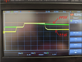
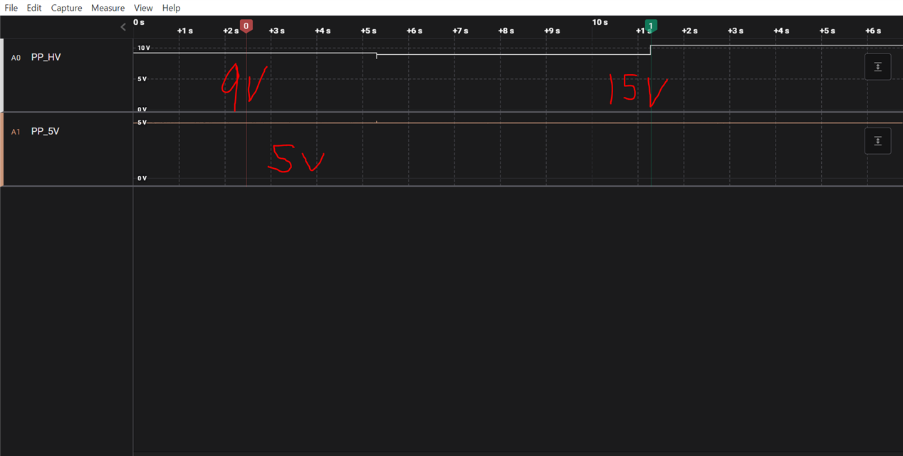
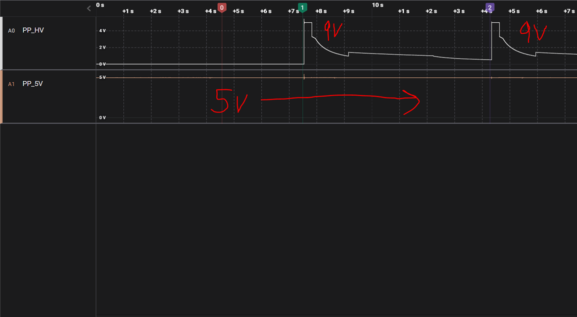
  2. When sourcing 5V/3A from the USB-PD-CHG-EVM-01 I would have expect the TPS25750 chip to request 5V from the BQ25792, but instead it seems to use a dedicated 5V buckboost that is also on the board. Is there any way to configure the TPS25750 to request the 5V from the BQ25792 and not the onboard TPS54531D? It seems excessive to have both of these chips.
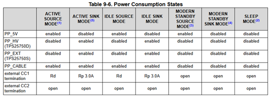
  3. Digging further into the documentation of this chip, the TPS25750D states that it has a "Integrated 28-V, 7-A, 16-mΩ bi-directional load switch", but in the rest of the documentation it does not seem as though it is capable of actually being "bidirectional". In table 9-6 on page 47 of the datasheet it says that while in active source mode, the PP_5V power path is the only one enabled. This seems to limit the sourcing capabilities of this device to a maximum of 5V unless you bypass the chip as has been done in the USB-PD-CHG-EVM-01 with the TPS54531. Can you confirm this is true? And would this limitation would be present for the TPS25750S and D variants?


  4. I have been digging through forum posts and documentation for using the USB-PD-CHG-EVM-01 as a higher power source and ran across this forum post: https://e2e.ti.com/support/power-management-group/power-management/f/power-management-forum/1245968/usb-pd-chg-evm-01-connection-failure-with-tps25750evm. In it there is mention of a new chip that is supposed to come out in Q3 of this year. What is the current status of this chip?
  5. What is the TI's recommended architecture for a battery bank that can source and sink up to 60W (ideally 100W capable)?

Thanks,

Nate

  • Hi Nate,

    1.) How are you loading the configuration? Are you using our web GUI (v7.0.4)? Please send me your project configuration file (.json for web GUI) so I can take a look.

    2.) When sourcing from the TPS25750D, 5V contracts will always source through the PP5V and TPS54531D path. This is necessary for internal functions. Any greater than 5V PD source contract will source through PPHV and the BQ25792 path.

    3.) The TPS25750D is capable of sourcing via the PPHV path. The PPHV path is indeed bidirectional. I am not sure about the table, but I would disregard it for now. The difference between TPS25750D and TPS25750S is that the D variant has two internal paths while the S variant has one internal PP5V path and one external PP_EXT (bi-directional) path.

    4.) The new chip mentioned in the other E2E thread is still due to release by the end of this year, likely around November.

    5.) The USB PD CHG EVM is limited to sourcing 45W due to the BQ part on the board. If you wish the source 100W, I recommend pairing TPS25750 with BQ25731 or waiting for the new chip to pair the new chip with the BQ25756. Both of these BQ parts can source 100W, but please note that the BQ25756 cannot be paired with TPS25750.

    Best,

    Alex

  • Hi Alex, I have already provided all the data you should need on my setup in this post:

    https://e2e.ti.com/support/power-management-group/power-management/f/power-management-forum/1266314/usb-pd-chg-evm-01-preferred-power-role-power-source-unexpected-behavior/4844071#4844071

    Refer to my message sent on September 7th for the test setup.

    Refer to my message sent on September 14th for the test data showing 27W not working. Please ignore the ASUS monitor dock data. It seems to be a special case. Not sure why yet.

  • 4.) The new chip mentioned in the other E2E thread is still due to release by the end of this year, likely around November.

    What will the specifications of this new device be, and are there likely to be delays in its release? I'd like to know for planning purposes.

    5.) The USB PD CHG EVM is limited to sourcing 45W due to the BQ part on the board. If you wish the source 100W, I recommend pairing TPS25750 with BQ25731 or waiting for the new chip to pair the new chip with the BQ25756. Both of these BQ parts can source 100W, but please note that the BQ25756 cannot be paired with TPS25750.

    Can you tell me how to configure the USB PD CHG EVM to source 45W? My requirements are:

    • 2S battery
    • Standard power profiles up to 15V/3A for both source and sink
    • Preferred power role source

    Is it possible to configure the TPS25750 to source 5V profiles through PPHV instead of PP5V? It seems redundant to have PP5V and PPHV driven by different ICs off the battery when the BQ25792 is capable of bucking to 5V.

    Nate

  • Is it possible to configure the TPS25750 to source 5V profiles through PPHV instead of PP5V? It seems redundant to have PP5V and PPHV driven by different ICs off the battery when the BQ25792 is capable of bucking to 5V.

    After further review of the datasheet, I do see that the 5V power supply is required for internal CCy line logic. Is this why the additional 5V supply chip is required?

  • Hi Nate,

    The 5V Source PDO must go through PP5V. This is required for internal circuitry such as CC line logic and internal gate drivers. The PP5V path comes up quicker than PPHV, which also contributes to why 5V must go through PP5V, to ensure timing of certain internal components. Currently, the TPS25750 does not support sourcing 5V PD contracts through PPHV. The BQ25792 may be capable of bucking to 5V, but our PD controller does not support sourcing 5V from the BQ part currently. This is a limitation of the device, and may be addressed in future updates of the new chip I mentioned. 

    I cannot share specs of the new device with you, as it is still unreleased. However, we do expect it will release no later than the end of November.

    Let me take a look at the json project file you sent in the other thread and check if your configuration is correct for sourcing 45W.

    Best,

    Alex

  • That makes sense, thank you for the detailed explanation.

  • That makes sense, thank you for the detailed explanation. I will attach a configuration in this chat to provide clarity. Please ignore the data in the linked post.

  • The profile I am currently using is this: 7245.config.zip

    This profile fails when trying to source anything above 5V

  • With the above configuration, all sinking profiles seem to work, but when sourcing more than 5V (9V and above) the bus seems to repeatedly get reset for some reason when connected to a pixel 3a, an ASUS laptop, and a lenovo laptop. I am wondering if it is because the PP5V line follows the PPHV line as it tries to ramp up to 9V as shown in the image below:

    This does not seem like normal behavior.

    Here is the data for the above pixel 3a sourcing test: Pixel 3a 9V failed negotiation.zip

  • Hi Nate,

    I took a look at the other thread you mentioned. Your project config json looks ok to me on initial scan.

    In the thread, you mentioned the battery size and a 5A max output. Can you confirm what the voltage of the battery is and what max current it can provide?

    Best,

    Alex

  • The battery I currently have attached to it is a 2S pack with a voltage range of ~7-8V. This pack is for testing purposes and can provide 5A for a short duration.

  • Hi Nate,

    How are you probing the PP5V on the CHG EVM? I am just curious because we don't have a test point for PP5V on the CHG EVM.

    If PP5V is ramping to 9V for 30ms like on the scope capture, this could damage that path and we likely do some sort of a shut off.

    Best,

    Alex

  • Hi Alex,

    I was probing from the PP5V side of the indicated capacitors below:

    I agree, it could do damage, and might reboot the chip, but why is it doing that? I have changed nothing with the PCB. It seems like it could be a software bug.

    When I reload the EEPROM with a 5V Source preferred power role everything works fine. Source and sink.


    Can you confirm that this chip (TPS25750) is capable of 9V and higher profiles for sourcing?

    Thanks,

    Nate

  • Hi Nate,

    It is possible that there is an issue with the CHG EVM you have. This does not look like a software bug to me or else we would see it with other CHG EVMs we have. This may be a hardware issue.

    The TPS25750 is capable of supporting a source PDO of up to 100W (20V 5A) with all greater than 5V sourcing done through PPHV. However, the PD only acts as a gate here, while the BQ battery charger part does all of the sourcing from the battery. The PD controller simply negotiates a PD contract,  enables/disables the power path on certain conditions, and programs the BQ part. Please ensure your BQ charge voltage and charge current is sufficient for your desired source PDOs. For example, if your charge voltage is set to 8.4V and charge current is set to 2A, the BQ part will only be able to source 16.8W from the battery, regardless of what source PDOs you have configured in the PD registers.

    To ensure the BQ part is sourcing the proper power, can you probe the SYS output of the BQ part. You may be able to probe it via J1 or another exposed pin such as at cap C17. If the BQ part is sourcing 9V while the PD shuts off, then this is a PD issue. If the BQ part shuts off at 9V, it could be a BQ part issue.

    Best,

    Alex

  • Hi Alex,

    There is a big difference to how quickly a battery can be charged vs discharged. It wouldn't make sense to tie these two together with the same requirements.

    Because of this my initial assumption on how the system worked is as follows:

    • Charging power is defined by the settings 10 and 11 in the Application Customization Tool and has no direct (power related) effect on what powers can be output from the battery.
    • Discharge power is defined by the setting 2 in the Application Customization Tool and is not effected by the charging limits of the battery but rather should adhere to the discharge current limits of the pack its self determined during design.

    Also, when reading through the documentation and observing the interaction between the TPS25750 and BQ25792 on I2C I have found the following:

    • The BQ chip has two separate registers for charge and discharge current limits. REG03_Charge_Current_Limit and REG0D_IOTG_regulation.
    • After POR of the system, the TPS chip sends the following I2C message to the BQ "0x03 00 C8" which writes the value of 2A to the BQ charge current limit register.
    • Once a connection is made to a device and a 9V contract is accepted, the message "0x0D 4B" is sent to the BQ chip. This writes 3A to the REG0D_IOTG_regulation register.

    Based off the above I do not think this statement is true:

    For example, if your charge voltage is set to 8.4V and charge current is set to 2A, the BQ part will only be able to source 16.8W from the battery, regardless of what source PDOs you have configured in the PD registers.

    Another point to add is that when I load a 5V3A preferred power role Source configuration to the USB-PD-CHG-EVM-01 with a charging current of 1A, the CHG-EVM is still able to source 5V3A even though it should only be able to output ~8W according to your above example. I understand this uses a different power path, but surely, if the logic you suggest is true, it would respect the 1A (~8W depending on battery voltage) for both power paths.

    I have also tried increasing the battery charge current to 5A. Which with your logic would suggest the system could output ~40W, but it still fails to negotiate 9V3A.

    Do you have the hardware to setup a simple test on your end? I suspect you will find the same results as me if you plug an 8V/5A power supply into the battery port on the USB-PD-CHG-EMV-01, set the charging voltage to 8V with a preferred power role source, and a 9V/3A sourcing profile. This will also help confirm if I have a broken board or not.

    If you are unable to test this on your end, can we setup a call to clarify the situation? If not I will have to explore other solutions.

    Thanks,

    Nate

  • Hi Nate,

    I was giving a suggestion using my understanding of the BQ part. I am not on the BQ team, so I am not extremely familiar with it. If you have questions about the BQ part, please open an E2E thread with the BMS-BCP team. 

    I have the hardware to test, but the 8V/5A power source may not have the same behavior as a 2S battery. But I can test with that setup and let you know the results.

    Ultimately, I do not have control over whether you explore other solutions. But of course we want to resolve the issue you are seeing. I will provide an update when I have test results.

    Best,

    Alex

  • Sorry Alex,

    I am just getting frustrated with this architecture and the support I've received from TI so far. I have been trying to get the TPS25750EVM and USB-PD-CHG-EVM-01 working for over a month now across various e2e posts.

    In these posts I have collected many datasets to address various issues without any progress being made. To me, it seems like this architecture just does not work as advertised.

    Perhaps I have a board that is broken, but I have no way of checking this.

    Sincerely,

    Nate

  • Hi Nate,

    I understand your frustration, but we are trying to resolve this. 

    The architecture works for the most part and should definitely work for sourcing >5V.

    I tested the sourcing capabilities of the USB PD CHG EVM today with your exact configuration json file (with 45W sourcing capability). By connecting a power supply configured to provide 8V 2A to the BAT connection of the CHG EVM, I was able to source a 5V contract on PP5V, a 9V contract on PPHV, and a 15V contract on PPHV with no issue. I also probed the PP5V signal exactly where you did (C27) and saw that it stayed put at 5V when a 9V source contract was negotiated. I have attached my captures to this post. Keep in mind the tool I used (Saleae) is limited to 10V.

    However, I did have an issue with sourcing a 9V contract when I used a different power supply, also at 8V 2A. With this power supply, the PD reset after negotiating a 9V contract, without sending PS_RDY. Even then, I did not see PP5V rise to 9V.

    From my tests today, it seems like sourcing behavior of the CHG EVM may be dependent on the battery source to the BQ part. When I tested, the CHG EVM had the jumpers set to 2S battery (JP1 and JP2 jumpers populated). 

    I believe there could be 2 reasons you are unable to source > 5v from the CHG EVM:

    1. The battery you are using is not providing proper power or not working well with the CHG EVM. Have you tried using a power supply to simulate the power coming from the battery? Or have you tried using a different battery? I would recommend trying this if you have not.
    2. The CHG EVM you have is bad. I did not see PP5V at C27 ramp up to 9V with PPHV. You should not be seeing this. If this occurs, the PD controller may reset due to overvoltage. I would recommend trying a different CHG EVM part or ordering another one if this is the case.

    Best,

    Alex

  • Hi Alex,

    Thank you for the detailed response. I really appreciate the example.

    The battery you are using is not providing proper power or not working well with the CHG EVM. Have you tried using a power supply to simulate the power coming from the battery? Or have you tried using a different battery? I would recommend trying this if you have not.

    I have tried, and just tried again, a power supply in place of the battery. The power supply was connected to J2 and provided 8.4V/2A. The loaded configuration was the one I shared with you on October 10th. This configuration did not work.

    Notes on this setup:

    • PSU voltage dropped 400mV during the transients as PPHV rose to 9V (this was measured at J2).
    • PP5V measured at C27 still ramped up with PPHV.

    I am confused by your selection of JP1 and JP2, when you look at the BQ25792 only 1 of these jumpers should be selected for proper battery configuration selection.

    All that said, it does appear that the chip on our USB-PD-CHG-EVM-01 is broken in some way.


    I also have a TPS25750EVM that I have been unable to get to source. It has basically the same behavior, however PP5V does not follow PPHV. I understand this EVM requires modification to be able to sink into a battery pack, but how can I get this EVM to Source more than 5V? 

    Currently I have the TPS25750EVM in the following configuration:

    • Micro USB plugged into my computer
    • J9 supplied with a 19.5V 4.62A power brick
    • J5 Populated
    • J2 Populated
    • J4 Populated
    • J1 jumper in position 2/3
    • Configuration and logs: TPS25750EVM not sourcing as expected.zip

    Thanks,

    Nate

  • Hi Nate,

    Sorry I meant JP4 and JP1 were populated during my test. It does seem like the CHG EVM board you have is bad though. PP5V should not ramp up with PPHV. This will cause OVP and reset.

    There seems to be some issues with the web GUI for TPS25750 that is causing the projects not to work for sourcing >5V. It was failing for me as well. I have attached a binary file that I created and verified works for sourcing >5V on the TPS25750EVM. Please try this binary file. You can still use the web GUI to flash the binary file (Flash from Binary File option). This will only work for the TPS25750EVM, not the USB PD CHG EVM.

    TPS25750_EVM_Source_Sink.bin

    Best,

    Alex

  • Hi Alex,

    This binary worked!

    When can I expect this bug to be fixed?

    Would this bug be present for both the BQ25731 and BQ25792 configurations?

    Nate

  • Can you send me a binary for the BQ25792 with the same configuration?

  • Hi Nate,

    I can work on getting you a binary with BQ25792. The bug may not be present for BQ25792 configurations, let me check that. Are you planning on using this with the CHG EVM? Keep in mind that the project configuration you used for the CHG EVM worked on my side, but failed on yours. So I still believe the CHG EVM hardware you have is bad (PP5V ramping with PPHV).

    We actually did not know about this bug, so we will work to resolve it now. It seems like there were some preset fields that were not updated when the TPS25750 EVM moved from another BQ part to the BQ25731 part. 

    Best,

    Alex

  • Morning Alex,

    I can work on getting you a binary with BQ25792. The bug may not be present for BQ25792 configurations, let me check that. Are you planning on using this with the CHG EVM? Keep in mind that the project configuration you used for the CHG EVM worked on my side, but failed on yours. So I still believe the CHG EVM hardware you have is bad (PP5V ramping with PPHV).

    We are planning on using the BQ25792 in our application.  I understand that the CHG-EVM we have is likely broken in some way, but I am unsure how long it has been broken. All I can say is the CHG-EVM has never worked for me and has always had identical symptoms to the TPS25750EVM that you have now fixed with the provided binary.


    We actually did not know about this bug, so we will work to resolve it now. It seems like there were some preset fields that were not updated when the TPS25750 EVM moved from another BQ part to the BQ25731 part. 

    Looking forward to the fix. For now, is it possible to request binaries from you?

    Nate

  • Hi Nate,

    I am attaching a binary for CHG EVM that I have tested and confirmed works for sourcing greater than 5V. CHG EVM uses BQ25792, so this binary includes BQ25792 specific configurations. Other than that, the configuration in this binary is the same as the previous binary I sent you for the TPS25750EVM.

    BQ25792_CHG_EVM_Source_Sink.bin

    While the TPS25750 web GUI is not working for new EVM configurations with BQ25731, you can request binaries from TI for BQ25731 setups. However, the web GUI is working for the CHG EVM, as confirmed by my testing. Further binaries for CHG EVM or BQ25792 setups should be obtained from the web GUI, unless further issues are discovered.

    Best,

    Alex

  • Hi Alex,

    I just received the USB-PD-CHG-EVM-01 and have the same issue as Nate.  What I have found is that the original EEPROM image works fine for sourcing at >5V.  But any image I create using the GUI will not source >5V.  Can you point me to a GUI that will create good binary images for this board?  My final design will use the TPS25750 and the BQ25798 and really need to get the EVM working so that I can confirm it provides the USB Type C CC functionality I require.  If you can create a bin from my json so that I can test functionality that would be great!

    Thanks for your help,

    Richard

  • Hi Richard,

    The version 7.0.4 web GUI is working for USB PD CHG EVM projects. GUI found below:

    https://dev.ti.com/gallery/view/USBPD/TPS25750_Application_Customization_Tool/ver/7.0.4/

    Below is a USB PD CHG EVM web GUI json file that I have confirmed to be working on my USB PD CHG EVM. We unfortunately do not support binary file generation for USB PD CHG EVM projects as the GUI is working for that application. The GUI can be used to generate the binary file. If you would like to use the one time binary file I have already provided in this thread above, you can do so.

    USB_PD_CHG_EVM_Source_Sink.json
    {"questionnaire":{"version":"7.0.4.6","answers":[0,2,3,0,0,null,1,null,1,null,0,8.4,2,0.04,0.04],"options":{},"configID":"0000","vendorID":"0000"}}

    As this thread is already resolved and was created by a different author, please create a new thread for further questions.

    Best,

    Alex