This thread has been locked.

If you have a related question, please click the "Ask a related question" button in the top right corner. The newly created question will be automatically linked to this question.

TPS54J061: stability calculation: datasheet vs calculator

Part Number: TPS54J061

Can you please comment on an apparent discrepancy between the stability criteria suggested by the datasheet versus the Excel calculator?

Datasheet:

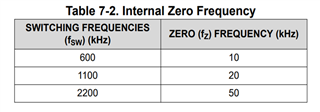
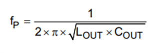
Plugging 4.7µH & 1µF in the calculator, with 60% derating, Fsw = 1.1MHz, results in "GOOD" stability, while the calculation with the datasheet the capacitor should be at least 15µF. Can you comment on that?

Thanks!

  • Hello,

    Can you please provide a screen capture of your excel calculator showing this. My data in the excel is not aligning with "GOOD" stability. And please elaborate on the datasheet calculation.

    Thank you,

    Calan

  • Datasheet calculation is very straightforward with the equation I listed for the pole frequency. With L= 4.7µH and C=15µF, the pole is at the limit with 19kHz.

    With the same inductor at 4.7µH and a 1.5µF bulk capacitor (plus 0.1µF MLCC at 60% derating) I get a "GOOD" at cell F104. Spreadsheet attached.

    Thanks.

    Copy of TPS54J06x_TPS54Jx20_TPS548x27-8-9_excelCalculator_RevA.xlsm

  • Hi,

    Thanks for providing this. Based on your excel, the Vout undershoot and overshoot are not within recommended values. The Cout and Lout are also not within recommended values. The calculator may be showing "GOOD" stability when the system might not be a recommended system. It could just be considered stable. I suggest to follow the criteria and conditions from the datasheet regarding minimum and maximum component values to ensure the best stability. 

    Best,

    Calan

  • I am afraid I'll have some difficulty explaining this to my customer. I modified the calculator so no pink results exist and yet the system is considered stable with 2µF instead of 15µF.  From your comments it seems you don't believe the spreadsheet has a problem, but rather the specific numbers I plugged in create an exception. It is not clear whether I should always ignore the stability criteria of the calculator or not. I attached a new spreadsheet for reference. TPS54J061 stability study v02.xlsm

  • Hi,

    Overall, the excel calculator has a much more complicated/ specific calculation method into calculating if a system is "stable". 2uF capacitance is not recommended for a system. The datasheet recommends a minimum output capacitance much greater than this. The spreadsheet calculation is more complicated and takes into consideration more variables to get "GOOD" stability. Although all the results are green, the values you listed are unrealistic for a system to be stable. The excel spreadsheet likely does not have a problem. The datasheet just has a more basic formula method that makes it easier for users to understand and apply. I highly advise the customer to first follow the datasheet conditions to achieve correct component values, then use the excel to double check results/ check anything that may be missing.

    Best,

    Calan