This thread has been locked.

If you have a related question, please click the "Ask a related question" button in the top right corner. The newly created question will be automatically linked to this question.

BQ24610: Battery not charging

Part Number: BQ24610


I recently solved an issue with Q5 and the IC exploding when the battery is installed (added more capacitance and TVS to battery terminal).  Now I have an issue where the battery is not charging (non-damaged board).  Status LEDs indicate charging should be happening.

Vin = 22V, VBATT(20V battery) = ~18.1V, PG and STAT1 LEDs showing (which should mean its charging), but there is no power going to the battery.  The entire board is only pulling 17mA.  Charge current should be up to 6A.

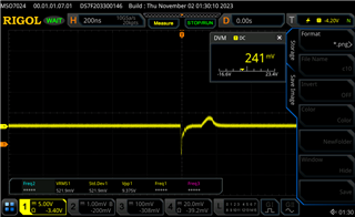
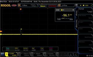
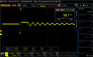
My PH and LODRV pins look like figure 7 (100% duty cycle and refresh pulse) in the data sheet.

Battery Charger circuit v2.pdf

  • Hi Jimmy, 

    Thank you for reaching out!

    Could you please provide additional information about your application?

    1- What is the battery cell count in your design?

    2- What is the adapter current limit?

    3- What is the intended precharge/termination current setting?

    4- What is the voltage at the TS pin? 

    Best Regards, 

    Aya Khedr 

  • Hi Aya,
    Thanks for the quick reply.
    1) Cell count 5
    2) AC Adapter?  ( right now I'm using a bench supply with 500mA limit).  Eventually we will use an AC adapter with at least 3A.  We were using a 19V 3.4A adapter, but I realized with the power path option, the battery (20V) will always provide power to the unit when inserted.  Both Q3 (P-CH for power path) and Q4 (NMOS of charging circuit) have the reverse diode feature, so as long as the battery voltage is higher than the input voltage there isn't any manual control to prevent the battery from running the system.

    If you're asking about the adapter limit setting (ACSET) then I have that set to 4A (same as figure 20).

    3) pre-charge/ termination setting is 300mA.  The same as figure 20 in the datasheet.
    4) TS voltage = 1.807V

  • Hi Jimmy, 

    It seems that your input power is too low for your desired application. 

    With these given parameters: VIN = 22V, 5-cell, Iadapter_limit = 500mA, Icharge = 6A, Iprecharge = Iterm = 0.3A

    Please see the calculation tool below. I have input the parameters listed above. 

    Notice R2 (battery charge voltage setting) and R8 (Battery fast charge current setting) do not align with the resistor values in your schematic. Also, the recommended LC output filter resonant frequency range is within 12-17kHz. 

    Please review and let me know if you have additional questions/concerns. 

    Best Regards, 

    Aya Khedr 

    BQ24610_Jimmy.xlsx

  • Hi Aya,

    I changed the C to 30uF in the LC circuit and updated R2 to 908k.  I also changed the adapter to output 2A.  I realize that this is not enough for the 6A limit, but I am still only seeing a sub 20mA pull from the bench supply (adapter).  I would expect that if the circuit was actually charging it should attempt to pull the 6A, even if it only get ~2A of draw out of the adapter.   Right now I'm getting basically no charge current.  Is there some mechanism that shuts the charge circuitry down if it doesn't get enough current draw?  If so how fast does that circuitry trigger?

  • Hi Jimmy, 

    No, there is no mechanism that would shut the circuitry if it doesn't get enough current. 

    What is the REGN voltage when the adapter output is 2A?

    Best Regards, 

    Aya Khedr 

  • Hi Aya,

    The adapter output never gets to 2A.  It never gets above 20mA.  That's why I need the help.  As far as I could tell the signals at the pins (mentioned above) tell me that the device should be charging up to the adapter current output level, but since it never gets above 20mA, something is wrong.  I would understand if we were charging even at 500mA, that would show that the charging circuitry is working, but since there is effectively no current draw, I'm not sure what is going on.

  • Hi Jimmy, 

    I meant to say when the adapter or bench supply is set to output 2A (basically when the board has power).

    I think we can take a slight step back and check some critical parameters: 

    • VREF voltage 
    • REGN voltage 

    It would also be helpful to provide some scope captures of the behavior you are seeing. Maybe a waveform of the switch nodes and a waveform of the STAT1 signal. 

    Best Regards, 

    Aya Khedr 

  • Hi Aya,

    STAT1 is solid low ~40mV.
    VREF = 3.3V
    REGN = 5.98V

    BTST

    LDRV

    PH

    HDRV

  • Hi Jimmy, 

    Thank you for providing the waveforms. The voltages align with the expected values as do the waveforms. 

    Do you have a source meter or a 4-quadrant supply that you could use to simulate a battery?

    Best Regards,

    Aya Khedr 

  • Unfortunately no I do not, but this is with the real battery connected to VBAT. The battery I connected has about 70% charge.  So it should be able to charge at the regular rate (not at the precharge or trickle rate).

  • Hi Jimmy,  

    Could you try increasing the power supply output to 24V at 2A? Does this change the observed behavior? 

    Best Regards, 

    Aya Khedr 

  • Hello Aya,

    When I set the output to 24V the current draw increases to from 18mA to 50mA.

  • Hi Aya,

    I tried making the above changes to another board and I think I found the issue.  I believe the LODRV FET is shutting down to thermal constraints (I believe the board I've been testing on has a damaged FET and so when I originally measured the FET temp is wasn't elevated.  I made the above changes to another board and got the charging current up to 150mA.  As the charging current continued to increase the FET on this board over heated in the process.  I will need to update the layout to allow for more thermal dissipation for the FET.

  • Hi Jimmy, 

    Thank you for the update. 

    Feel free to open a new thread after updating the layout and I would be happy to review. 

    Best Regards, 

    Aya Khedr