- Ask a related questionWhat is a related question?A related question is a question created from another question. When the related question is created, it will be automatically linked to the original question.
This thread has been locked.
If you have a related question, please click the "Ask a related question" button in the top right corner. The newly created question will be automatically linked to this question.
Hello Binoj,
Thank you for your interest in the UCC28180 PFC controller.
I'd like to help you and I need more information.
First, please attach the schematic file. It does not appear in your original posting.
Second, please attach the filled-out Excel Calculator Tool. If you have not done this, it can be obtained here: https://www.ti.com/tool/download/SLUC506
Can you verify that with L3 = 600uH switching at 65kHz you can obtain Pout = 1000W?
Is there a power level where the PFC works okay at 140kHz? Such as: works okay from 0W up to 600W output, MOSFET fails for Pout > 600W. Or something like that?
Finally, you mention stage 1 is AC input to 400V DC output. Stage 2 is 430Vdc input to 230Vdc output. Which is the correct PFC output voltage, 400 or 430 V?
Regards,
Ulrich
Hello Ulrich,

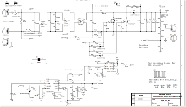
Thanks for your support. The above image is the PFC design. Do we have option to attach a pdf? We were not able to drive more than 100 KHz around 500W output. PFC stage output is 400V, by mistake it is mentioned as 430 V. I am working on the excel calculation sheet .Once completed I will share you. Thanks.
Regards
Binoj
Hello Binoj,
Thank you for the schematic image and additional information. A PDF file can be inserted by selecting the Insert tab of the menu below the dialog box and then choosing the Image/video/file option to browse to your file location and select it.
I look forward to receiving your Excel file.
In your posted schematic, I noticed that your gate-drive turn-on resistors R43 and R44 are 100 Ohm (100R) each. This high value will significantly slow down the turn-on dvdt of the MOSFETs. This slow turn-on rate may be allowing higher switching loss which may be overheating the MOSFETs when run at 140kHz.
I suggest that you try using lower resistance, such as 22R to see if speeding up the turn-on can alleviate the MOSFET failures.
Regards,
Ulrich
Hello Ulrich,
Thanks for your feedback. I will check with a small value resistor on gate drive as you suggested. Kindly find the excel sheet with design parameters.sluc506cupdate.xls
Regards
Binoj
Hello Binoj,
I hope your test results with lower-value gate resistance are positive.
Thank you for the spreadsheet file. I noticed several discrepancies that I would like to clear up:
1. In your first post (above) you listed 1000W as your output power rating. The spreadsheet indicates 1250W. What is the true power target?
2. The schematics image above shows Rsense = 40mR||40mR = 20mR. For 1250W, the spreadsheet requires 16mR and to keep ICOMP < 5.7V, it requires Rsense to be ~11mR. What value is actually on your test board?
3. 140kHz requires 15kR at the FREQ pin. The schematic shows 20kR, which is ~105kHz. What frequency are you actually running at?
4. Spreadsheet shows Lbst(actual) = 223uH. Your comments above indicate 200uH. What value is actually used?
5. Your comments indicate 400V output target. Schematic and spreadsheet VSENSE resistors indicate ~386V. What is actual design target? (Note: 386V regulation target will not work with 275Vac max input.)
There may be others that I have not found. It is important to provide accurate information on values and test conditions to avoid confusion.
However, in this case none of the discrepancies account for failures of the MOSFET and driver.
I suspect that MOSFET failure occurs first and takes out the driver as a consequence. We need to determine what stress is causing the MOSFET failure.
Basic stresses are:
drain current too high => leads to excess junction temperature => leads to breakdown and failure
heat-sinking too small => leads to excess junction temperature => leads to breakdown and failure
drain or gate voltage too high => leads to breakdown and failure
MOSFET voltages and currents are easy to observe to see if any are exceeding the MOSFET ratings.
Junction temperature is more difficult to determine; based on calculation from heat-sink temperature measurement, thermal interface estimate, and power loss estimate.
Regards,
Ulrich
Hello Ulrich,
I have noticed that our design has many discrepancies while I fill the excel sheet. The maximum output rating required is 1200 Watts. Sorry for the confusion.
Let me correct the board with the findings . Hope that will resolve the issues. After testing I will get back to you. Thanks for your very good support.
Regards
Binoj
Hello Binoj,
I hope your testing is going well,
It has been ~3 weeks since your last reply. If no further support is necessary, please let me know and I will close out this thread.
Regards,
Ulrich
Hello Ulrich,
I have redesigned my PCB as I have found some issues related to return paths and placement. It is in the fabrication stage .Once I populate and test I will let you know the results. All the recommendations from your side I have incorporated in the new board. Hope it will perform well. We can close the thread time being . Thanks for your kind support
Regards
Binoj
Okay, Binoj.
Let's hope that your issues have been resolved in the new layout.
I'll close this thread.
Please open a new one if you experience problems with the new board.
Regards,
Ulrich
Hello Ulrich,
Thanks for your support. I will get back to you if I face any problem in my board. Thanks
Regards
Binoj