This thread has been locked.

If you have a related question, please click the "Ask a related question" button in the top right corner. The newly created question will be automatically linked to this question.

UCC2897A: Application to three phase power supply

Part Number: UCC2897A
Other Parts Discussed in Thread: UCC2894

Hellow ,

I would like to design a offline power supply using forward converter topology. 

The specifications are as follows

Input voltage: 280V to 330V

Output voltage: 100V

Power rating: 400W

Topology : Forward 

IC:UCC2897A

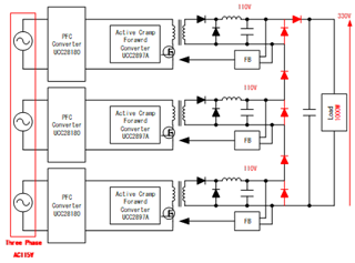
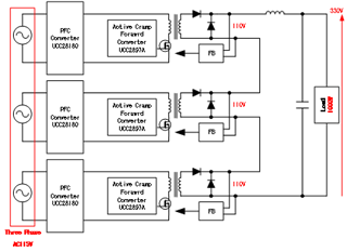
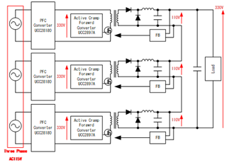
I am thinking about the circuit diagram such as the chart below, is this constitution possible?

In addition, is it necessary to add diodes for rectification?

Thanks and Regards

Tomohiro Yoshimura

  • Tomohiro-San

    The UCC2897A is intended mostly for telecom input voltage (36V<VIN<80V) applications. UCC2897A can be used for off-line power conversion but you would not be able to take advantage of the integrated 110V start-up JFET. A better choice for off-line, active-clamp forward PWM would be UCC2894 which has similar functionality but intended to drive a high-side N-channel, clamp MOSFET most commonly used arrangement for off-line power conversion.

    400W is high power for active clamp forward. You can use multiple controllers/power stages as you are proposing or you could possibly achieve this more effectively with LLC (regulated input and output voltage) or PSFB topology.

    The forward converter is really an isolated buck converter. Could you build a buck converter without using the high-side MOSFET and freewheeling diode? The answer of course is no, and the same is true for the forward converter output rectifier diodes...they must remain in the circuit.

    Regards,

    Steve

  • Hello,

    Thank you for your answer.

    I have additional question.

    Is the red diode of the lower figure necessary for rectification and protection?

    Thanks and Regards

    Tomohiro Yoshimura

  • Not necessary for rectification but could be used for clamping protection between the three outputs.

    Steve

  • Hello,

    Thank you very much.

    Then, is the design of the active clamp forward circuit possible by the constitution of the lower figure?

    Thanks and Regards

    Tomohiro Yoshimura

  • Hello,

    Yes, you are showing three different active clamp power converters where you want to connect each output in series to increase the total voltage capability. If this is what you want to achieve, you would also require each converter output to have it's own output LC filter and not sharing a common LC filter like what you are showing. You could then make the series connection after the output capacitor of each converter.

    The outputs can only share a common LC filter when each of the individual converter outputs are connected in parallel after the output rectifiers and then share a common LC filter. You would then have a single feedback to regulate the output voltage and this is done to increase current capability but then you have to consider how best to load share. 

    Regards,

    Steve