
- Ask a related questionWhat is a related question?A related question is a question created from another question. When the related question is created, it will be automatically linked to the original question.
Hi TI,
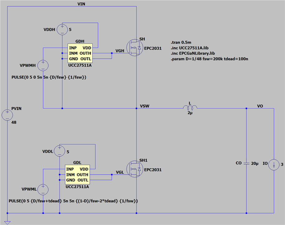
I built a half-bridge buck converter as shown below using EPC2031 switch and UCC27511A as driver for both high side and low side switches.
For the low side gate driver the ground node is connected to the power ground (GND symbol), and the ground note of the high side gate driver is connected to the switching node (VSW) to drive floating high-side switch.
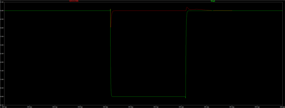
When the VGS of two switches are plotted, the output of the low side gate driver (green) is correct, switching between 0V and 5V.
However, the VGS of high-side driver (red) is incorrect, and it's fixed at 5V, even though there is a input PWM signal complementary to the low-side driver input.
Is this the expected behavior of the part UCC27511A?
If the differential voltage bias between each input ports are the same as low-side gate driver, shouldn't the high-side gate driver operate in the same manner as the low-side one?


