This thread has been locked.

If you have a related question, please click the "Ask a related question" button in the top right corner. The newly created question will be automatically linked to this question.

TPS65987D: Data role changing during power role swap

Part Number: TPS65987D


Hi,

We have a design that is essentially a USB hub as shown in the attached block diagram. The essential behaviour required is:

o The upstream facing port is permanently connected to a battery powered Host via a captive cable. The Host is always required to be a DFP.
o The two downstream facing ports have identical functionality and can be either connected to a USB-PD power adaptor (like an Apple 65W USB-C power adaptor) or to a USB Mass Storage device like a USB3.1 SSD drive.

The normal use case is that:

o A USB-C power adaptor is plugged into DS1 which powers the hub and charges the Host while the Host (always as a DFP) has USB data connectivity to the USB Mass Storage device.
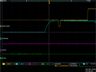
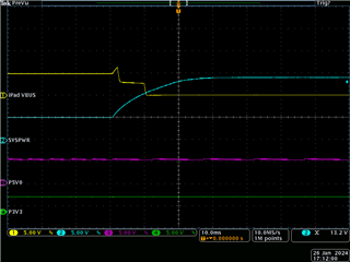
o If the USB-C power adaptor loses mains power, or its USB-C cable is unplugged from the hub, the Host is required to do a Fast Role Swap to switch from charging to sourcing 5V@3A to maintain power to the hub and also maintain uninterrupted USB data connectivity with the USB Mass Storage device.
o When mains power is restored to the USB-C power adaptor, or its USB-C cable is plugged back into the DS1 port, the Host should swap back to being charged while it maintains uninterrupted USB data connectivity with the USB Mass Storage device.


The issue I am seeing is that when the USB power adaptor is attached, the correct behaviour is normally seen with the Host swapping to being charged and the data connectivity of the Host to the USB Mass Storage device is maintained uninterrupted. However, sometimes it gets into a state where incorrect behaviour is seen with the data connectivity from Host to USB Mass Storage device is lost when the Host swaps to being charged and then the USB Mass Storage device re-mounts automatically a couple of seconds later. It seems to remain in this odd state but if a "PD Hard Reset" 4CC command is issued to the Host PD Controller via I2C, the normal behaviour is restored.

Unfortunately, if I put a PD protocol analyser (a Lecroy T2P) in between the Host and its PC controller, it seems to change the behaviour itself, so I am unable to check what PD messaging is going on to try and debug the issue.

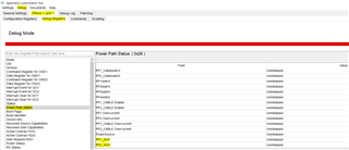
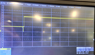
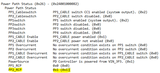
I have attached a scope screenshot of the "correct" behaviour and one of the "incorrect" behaviour. I have also attached the TPS65987D Application Customisation Tool project file for the Host PD controller.

There appears to be no issue with continuity of power for the hub and muxes in the USB data paths so I suspect that the Host is temporarily switching data role from being a DFP to a UFP when the power role swap from source to sink occurs.

So any advice would be much appreciated on:

o Is there anything in the power architecture or use of TPS65987D power path switches shown in the block diagram that could be an issue?
o Are the project customisation settings correct to achieve the desired behaviour for keeping the Host as a DFP data role while the power role swaps from being a source to a sink for charging?

ThanksPD Hub block diagram.pdf  TPS65987D Host config.pjt

  • Hi Gerry,

    Looking at your block diagram it looks like you are using multiple devices. Are you using the same configuration for all of these? It may help if you create separate projects that make these devices strictly for UFP or DFP. In the project file you sent me it and based on your comments, you want it do be DFP only, but in the port control registers (0x29) you had selected (or it was already selected) 'Process Swap to UFP' and 'Initiate Swap to UFP'. It may be helpful to change these to the respective ones for DFP instead as you mentioned DFP only, and may halt this process.

    Is this happening with FRS (fast role swap) or power role swap?

    I know you discussed about the PD logs, but would it be possible to get these? It looks like there is may be a disconnect, similarly seen in a fast role swap, but it doesn't process in time. So please look into the above if you can, and provide me a PD log that I may look at.

    Thanks,
    Field

  • Hi Field,

    Thanks for the quick response and suggestions.

    Regarding projects, the Host facing PD controller has its own project in which I have tried to tell it to be a UFP only (from the PD controller's perspective with the Host being a DFP only, unless I have misunderstood the terms and am using the incorrect settings. I thought that setting 'Process Swap to UFP' and 'Initiate Swap to UFP' told the Host PD controller to be a preferred UFP, so the Host would always be a DFP? The two downstream facing ports (DS1/DS2) have identical projects which is separate from the Host PD controller. I believe the DS1/DS2 PD controllers are behaving as expected.

    The issue with the data role changing is only happening during the power role swap when the Host changes from supplying 5V to the hub to being a sink at 15V for charging the Host.

    I'll have a look at any logs I can capture.

    Thanks,

    Gerry

  • Hi Gerry,

    I see, so the PD controller is meant to be UFP only. Apologies for my confusion. Could you go into the application tool and select 'Port Settings' at the top, then select the 'Port Configuration' and look for the field labeled 'Port Configuration' and change this value from DRP to UFP (or the one which is desired)? This may help. 

    The PD logs would still be helpful.

    Thanks,
    Field

  • Hi Field,

    Thanks for the further thoughts. I haven't tried the Port Configuration change yet or got any further with trying to capture the PD messaging with the Lecroy T2P protocol analyser, but I think I may have found what is causing the issue but can't quite see why yet.

    What seems to be happening is that when the SYS_5V power rail is just powering the on-board hub circuitry, the "correct" case occurs as I originally posted in the "correct" scope trace capture, but if I load the DS2 5V port say with just 200mA it seems to cause the "incorrect" behaviour as I originally posted in the "incorrect" scope trace capture.

    It seems that on inspection of the Host VBUS waveform for the "incorrect" case, the Host VBUS voltage seems to be following the increase in SYS_PWR voltage until presumably an over-voltage protection event occurs and opens PP_HV1 switch, as if PP_HV1 is not reverse blocking.

    I have re-captured these two cases of behaviour with GPIO18 configured with the "PP1 Switch Event" in order to see state of the switch on the scope, and configured the "Interrupt Mask for I2C1" to enable the  "Error: Power Event Occurred" to also display on the scope. I have attached these "correct" and "incorrect" scope traces.

    USB power adaptor attach cable - monitor error IRQ - low load on SYS_5V.png - shows expected correct behaviour

    USB power adaptor attach cable - monitor error IRQ - higher load on SYS_5V.png - shows the "incorrect" behaviour with PP1 switch state and I2C interrupt configured for "Error: Power Event Occured".

    USB power adaptor attach cable - monitor error IRQ - higher load on SYS_5V - zoomed.png - zoomed in version of the "incorrect" behaviour

    The I2C interrupt trace activity seems to suggest that an over-voltage protection event has occured due to SYS_PWR forcing the Host VBUS and PP_HV1 switch is subsequently opened.

    In the application customisation tool project, I set "PP1 Switch Config" to "PP Switch as Sink or Source" as shown in the system block diagram (and in the original project file I posted). The TPS65987D datasheet suggests that the switch should reverse block using comparator mode when the switch is used as a source, and uses the ideal diode mode when the switch is used as a sink.

    My question is, should this reverse blocking still work when the switch is configured as "PP Switch as Sink or Source", as it looks like this is no reverse blocking in this mode, unless I'm missing something?

    I'm still trying to find out why this issue is dependent of the loading of the SYS_5V rail and can't see any obvious link and the supplies seem to steady during this behaviour.

    Thanks,

    Gerry

  • Hi Gerry,

    Thanks for the response and information. I am not quite sure, and need to consult with a more senior device expert about this issue. However with the holidays this week, they are currently out of the office. When they return I should be able to discuss this, look into this further, and provide you a response. Please expect some delay accordingly.

    Thanks,
    Field

  • Hi Field,

    Just wondered if there's any information available yet about my key question. I've realised I should have phrased it a bit better to be clear about what I think might be the issue. The re-phrased question is:

    Should reverse blocking should still work when the switch is configured as "PP Switch as Sink or Source" ** and the switch is acting as a Sink **, as it looks like there is no reverse blocking in this mode, unless I'm missing something?

    Thanks for your help.

    Best regards,

    Gerry

  • Hi Gerry,

    I just got back to the office today. And can look further into anything else.

    Should reverse blocking should still work when the switch is configured as "PP Switch as Sink or Source" ** and the switch is acting as a Sink **, as it looks like there is no reverse blocking in this mode, unless I'm missing something?

    Yes, I believe there should be reverse current protection when the switch is acting as a sink or source. When it is PP switch as Sink or Source, the device should ideally be either sinking or sourcing which should fall under those parameters you mentioned above and seen in the datasheet about the ideal diode protection or comparator protection. But you mentioned this problem occurs from the PP_CABLE, so maybe it has to deal with that over current protection? But I will need to dive further into this.

    Thanks,
    Field

  • Hi Field,

    Thanks for the confirmation that switch reverse blocking protection should still be active in the "PP Switch as Sink or Source" configuration I've selected. Could there be some other configuration setting in my project that could defeat the reverse blocking protection?

    I'll have to double check if I've got some other inadvertant path that might be bypassing the internal switch. I don't believe i have a PP_CABLE over current issue that I am aware of but I'll double check.

    Thanks,

    Gerry 

  • Hi Gerry,

    I don't immediately see any settings to change or manipulate these values or operations. What may help, can you:

    1. Go into debug mode in the Application Customization Tool/GUI
    2. Proceed to the following section: 
    3. Run your processes again, and check the above.

    This may help provide some insight. It may also help to check the other sections for events which correspond to high voltage or overcurrent. These can be found in the TPS65987D TRM linked here and by searching for 'overcurrent' or 'highvoltage', or by using the ACT/GUI and while in debug mode and debug registers searching for the above accordingly. 

    Thanks,
    Field

  • Hi Field,

    I have replicated the reverse blocking issue on the TPS65987EVM in order to setup the simplest test to investigate the problem more easily.

    I've realised that the case title "Data role changing during a power role swap" is probably not the correct title now, as I believe the data role changing is a consequence of an over-voltage protection event occuring and initiating the error recovery sequence which I believe does a cable disconnect and re-establishes the cable connection. So I believe the topic is better described as "Reverse current protection operation of power path switches".

    I've captured the EVM behaviour which basically shows the same behaviour as included in the very first post. I have attached the application customisation tool project used, a block diagram of how the EVM power paths are used (which is the same as our product) and two scope traces: one showing what I believe is the expected behaviour and one showing the power path issue.

    I have configured GPIO5 and GPIO6 as "PP1 Switch Event" and "PP2 Switch Event" which are shown in the scope traces to confirm what the switches are doing. GPIO21 is configured as "Barrel Jack Detect" and I've changed EVM resistor R121 to 11K to change the barrel jack detect SYS_PWR threshold voltage to 12.5V to work with the 15V PSU input.

    The first scope trace "EVM as 5V 15V sink source with iPad - no SYS_PWR load.pdf" has no load on SYS_PWR and the PP1 switch appears to reverse block correctly as SYS_PWR ramps up to 15V. However, the second scope trace "EVM as 5V 15V sink source - SYS_PWR load 0.5A.pdf", which has a 0.5A load on SYS_PWR, shows that SYS_PWR appears to be passed directly through to the iPad VBUS when PP1 switch should be operating as a sink path. I still don't understand why the 0.5A load should change the reverse blocking behaviour of the PP1 switch.

    The point at which the iPad VBUS is turned off is directly related to the "Over-voltage Protection Usage" setting in the Port Config Register (0x28) which I have set to "Disconnect VBUS if voltage exceeds 15% of expected max". As this feedthrough of SYS_PWR to VBUS is a direct DC event as far as I can see, and there is no PD messaging occuring at this point, I assume it is the hardware over-voltage mechanism in operation. Although I still don't understand why there is the dependency on the SYS_PWR load.

    The customisation project uses the "TPS65987DDH (Advanced)" template. I've also tried using the "Standard (Recommended)" template and this seems to show the same behavour.

    Any further thoughts on this power path arrangement beahviour or the application customisation settings would be much appreciated.

    Best regards,

    Gerry

    EVM as 5V 15V sink source with iPad.pjt EVM 5V 15V sink source with iPad - no SYS_PWR load.pdfEVM 5V 15V sink source with iPad - SYS_PWR load 0.5A.pdf

  • Hi Gerry,

    Thanks for the in-depth information and providing these captures. I will go ahead and take a look at this with the EVM and see if I can find anything further and will consult with other experts to give you better information and insight. However, I will be out of the office later this week and won't be able to provide a response till early next week and apologize in advance.

    Thanks,
    Field

  • Hi Field,

    I hope you had a good break and happy New Year.

    I wondered if you've had a chance to look into our reverse blocking issue as this is becoming quite critical for us to resolve?

    Best regards,

    Gerry

  • Hi Gerry,

    Thank you, and I hope you as well. Unfortunately I will be on PTO and out of office until after next week, so I am trying to work on looping in another expert that may be assist in my absence.

    When testing this using your ''EVM as 5V 15V sink source with iPad.pjt'': 

    • I used a TPS65987EVM (#1) as similar to what you have laid out above. Using the J5 SYS_PWR pin for the operations involving the SYS_PWR as you described.
    • I used another EVM (#2) that acted as the iPad, with 1 source PDO of 5V 3A, 2 sink PDO of 5V 3A and 15V 3A and selected for both the process/initiate swap to sink, and no selection for that as the source so the device would only swap to sink when we are powering SYS_PWR as you described.
    • I used a programmable power supply set to 15V 2.5A and I used a DC E-Load set to 0.5A
    • When using no load:
      • Using the #2 EVM as a source and #1 EVM as a sink, and then turning on the power supply thus switching #1 to a source and #2 to a sink, I was able to get 15V on VBUS. And is seen similar to your ''EVM 5V 15V sink source with iPad - no SYS_PWR load (1).pdf''
    • When using the 0.5A load:
      • The same processed as described above, but while using the E-Load set to 0.5A turned on. I was able to get ~15V on VBUS, and the device responded accordingly to what is desired. This is seen similar to the above shot, but provided below:

    Looking at the load picture you sent, your device doesn't turn back on as seen in "EVM 5V 15V sink source with iPad - SYS_PWR load 0.5A (1).pdf", Which may be a problem with VIN3V3 and/or VIN5V0 not being provided. During this problem that you are seeing, there may be something happening to the Buck/Boost or the variable DC/DC, what are the levels here on VIN3V3 and VIN5V0? Additionally what is the current you are using on your power supply? What is the position of your EVM switches and jumpers (S1, S4, J4, J5)? 

    Additionally based on my results, since I am not seeing the similar behaviour, I may be doing something different with my testing procedures when I try to replicate what you are seeing. Please let me know if so. 

    Thanks,
    Field

  • Hi Field,

    Many thanks for your test results with EVMs. If anyone else can assist in your absence that would be much appreciated.

    Regarding my EVM switch and jumper positions, this is what I have in my setup:

    S1 switchS4 switchJumpers

    For the 15V PSU I'm using to feed the EVM SYS_PWR, it's set to 2A.

    That's interesting that your trace for the VBUS to the "iPad" EVM doesn't seem to show the same rising voltage when SYS_PWR is applied that I seem to be seeing. I'm fairly certain that VIN3V3 and VIN5V0 are stable and uninterrupted but I will double check.

    It would be interesting to know if you increased the 0.5A load as far as is allowed, whether the behaviour is still good?

    Best regards,

    Gerry 

  • Hi Gerry,

    We are still seeing who can fill in for Field while he is out this week. Please give us some time to look over the thread.

    Thanks and Regards,

    Chris Lim

  • Hi Chris, Field,

    Do you have any further suggestions regarding this reverse blocking issue?

    I have independently followed Gerry's instructions, using linked project 'EVM as 5V 15V sink source with iPad.pjt' on my EVM, and have observed the same behaviour as Gerry. Please see attached scope captures (with the electronic load off the power path behaves as expected, with the electronic load enabled at 500mA constant current the power path does not reverse block, and SYSPWR passes through to iPad VBUS resulting in an over-voltage condition).

    On my EVM I have replaced R121 with 11k (barrel jack threshold set for 15V input). Jumpers/switches are exactly as per Gerry's photos above. I have included P5V0 and P3V3 on the scope captures to show that these are stable during the power role swap.

    Any further information or suggestions would be graetfully received - this is a serious problem for us and is preventing our product from functioning as intended.

    In parallel to this query we would appreciate some support on our seperate query relating to Fast Role Swap trigger mechanisms (https://e2e.ti.com/support/power-management-group/power-management/f/power-management-forum/1312125/tps65987d-fast-role-swap-triggered-by-uvp-or-gpio-frswap-input-event)

    Many thanks in advance,

    David

  • Hi David,

    Thanks for providing these. Was my testing method accurate from my earlier post? I am currently OOO and will return tomorrow and will see if I can make some changes to the configuration to resolve this, but since I can not replicate the issue currently, I can't test for a fix. 

    Would it be possible for you to try using the EVM as the ''ipad'' that will swap from source to sink (connected to your design) instead of the iPad? 

    Thanks,
    Field

  • Hi Field,

    Many thanks for your continued support with this matter. Appreciate that it is difficult to provide support if you cannot reproduce the issue.

    I believe the testing method you've outlined is accurate. In our testing we've reporiduced the issue using an iPad with the TPS65987EVM and using an iPad with our custom hardware. We've focused our investigations on the UFP (as it's clear from the oscilloscope traces (above) that the iPad VBUS and SYSPWR traces directly overlay until an over-voltage threshold is reached).

    I will acquire a second TPS65987EVM and use this to provide the iPad functionality, as per your test set-up. In order to expediate this, are you able to provide the .pjt file you used for this purpose?

    With kind regards,

    David

  • Hi David, 

    I just wasn't sure if you could use the EVM as the "iPad", with your original design, so you would only need one. 

    I am using the following configuration file for the ''ipad'' EVM: Gerry_EVMipad_test.pjt

    When testing a few minutes ago, there looked like there was some trouble (but perhaps it was different than what you were seeing) when load current = max supply current, but when I lowered the value of the load current the trouble I was seeing went away (this looks like it might also be the case as when Gerry tested earlier they were doing something similar). However during this the load and power supply did say they were still providing, but the oscilloscope showed low voltage level. Could this be a possibility of what you are doing or seeing? Could you try increasing the supply level and seeing if the issue is still seen?

    Thanks,
    Field

  • Hi David,

    Is it possible after you and while you see this issue, can you go into the application customization tool/GUI while connected to the device and grab some debug logs for me? You can do this through the tool by going to the top tab labeled 'Debug' then going to 'Debug Mode'. After selecting this go to the top tab of 'Debug' and select/use the option for 'Take Snapshot'.

    Thanks,
    Field

  • Hi Field,

    Many thanks for your recent comments.

    I have not yet had a chance to test your iPad configuration (and replace the iPad in my set-up with a 2nd EVM), however will do so next week.

    Meanwhile, the reverse blocking issue we're experiencing continues. I have increased the PSU voltage slightly to overcome the diode/distribution losses, and verified the voltage being received by the iPad is 15V (reported as 15.0V at the iPad, reported by the in-line power meter, please see attached photo of my set-up). In this configuration the EVM is directly passing through the 15V from the PSU to the PP1 SRC path. The bench PSU current limit is significantly higher than the required current (the source PDO to the iPad is 0.5A, the electronic load is set at 0.5A and the PSU current limit is > 2A.

    I have captured and attached snapshots as requested. These are configured as follows:

    1.zip - PSU off, iPad acting as SRC (EVM as sink), electronic load off. No issues observed.

    2.zip - PSU on, iPad acting as SNK (EVM as sorce), electronic load off. No issues observed.

    3.zip - PSU on, iPad acting as SNK (EVM as sorce), electronic load on, 0.5A. Reverse blocking issue (and resulting over-voltage/link reset issue) observed.

    I would be interested to know if you can determine anything from these files.

    Please let me know if I can provide anything further.

    With kind regards,

    David

     1882.zip2.zip47848.zip

  • Hi David,

    As has been discussed it looks like the RCP is active, but only on PP_2, which is only set for the 5V source. (Assuming you are using EVM as 5V 15V sink source with iPad.pjt) and this could be what is causing what is seen.

    Could you try using the following .bin file provided below (when using your current setup of the EVM + iPad) and let me know if it alleviates anything that is being seen? I developed this from the .pjt I mentioned above, if you are using a different .pjt with the EVM, and seeing this issue please let me know. This may prove unsuccessful but is worth looking into:

    https://e2e.ti.com/cfs-file/__key/communityserver-discussions-components-files/196/David_5F00_E2E_5F00_1_5F00_05FEB.bin

    After discussing this with another expert, it is believed that perhaps the levels on VBUS when trying to source from the other side are greater and is causing this issue. One of the ways mentioned was to control the levels on VBUS when this is occurring or through the timing as the source supply is starting to ramp up and thus trying to swap roles. But the .bin file above, or some changes to your .pjt that I can guide you through, or testing with another EVM will help shed some more light on the issue.

    Thanks,
    Field

  • Hi Field,

    Many thanks for your input on this - I think we are making progress.

    It is odd that Reverse Current Protection is only active on PP_2 in the debug log above. We certainly require RCP on PP_1 - the case we are concerned with is when PP_1 is acting as a SNK (5V supplied from iPad VBUS conducting through PP_1 to SYS_PWR), and SYS_PWR is then raised above 5V by an external source.

    You are correct in your assumption that I'm using project file 'EVM as 5V 15V sink source with iPad.pjt', provided above.

    I have run the binary 'David_E2E_1_05FEB.bin' in my set-up - the behaviour has changed and I believe the reverse current issue is no longer present. Please see attached screenshots from scope - there is no longer evidence of an over-voltage condition on VBUS (in comparison to the previous screenshots that I provided). The iPad does now fail to establish a steady-state SRC contract from EVM however - it appears to oscillate between SNK and SRC states (see attached screenshot).

    It would be useful if you are able to guide me to configure the RCP feature correctly for our application via the Application Customisation tool - and if there is anything you have adjusted within the .bin file supplied that is preventing us reaching a steady-state SRC contract.

    Please let me know if there is anything further that I can provide.

    With kind regards,

    David

  • Hi David,

    That is good to hear, but I am curious if we aren't seeing it because it can't establish the contract. Let me verify that I can get 5V+ (specifically the 15V contract) and give you what I can find. I hope to have this information for you by end of business tomorrow.

    Thanks,
    Field

  • Many thanks Field - I look forward to hearing your findings. If I can provide anything further (e.g. LeCroy captures) don't hesitate to let me know.

  • Hi David,

    For the EVM + iPad, can you test the following .bin file I have provided at the bottom? With this I was able to negotiate to 15V as seen in the picture below. Hopefully the RCP issue is not seen. If this alleviates, then I can elaborate more.

    https://e2e.ti.com/cfs-file/__key/communityserver-discussions-components-files/196/David_5F00_E2E_5F00_2_5F00_07FEB.bin

    Thanks,
    Field

  • Field,

    Using the file 'David_E2E_2_07FEB.bin' I am able to establish a 15V contract (sourciung to iPad). On first connection of the 15V source the system behaves as intended (no RCP issue is observed and a 15V contract is established - see image 'tek00013 - correct.png'). However, on subsequent connections of the 15V source, the RCP issue returns (see image 'tek00014 - incorrect.png') - it seems the RCP feature is becoming disabled for some reason?

    Many thanks,

    David

  • Hi David,

    Yesterday before sending you the binary file, I believe I was able to replicate what you were seeing, (and saved the binary file for that) but I was able to resolve it with that binary #2 that I most recently shared, so this is interesting.

    Above you can see the similar behaviour, although this is from just sourcing (no swap from sink to source). I'll re-test though and check the debug logs to see if the RCP is active here as well to ensure it is similar. But when editing the configuration, to change it into the binary file provided I did not see this, and is the result I provided earlier. 

    Would you be available for a call to go over this? If so my email is f-tolson@ti.com. This way I can ask you some questions(mainly the ones from below or other that I may have between then), show you with some of things I am looking at, possible solutions, etc.

    • Is this first one with the load attached too?
    • Is the second scope shot from turning the device off, unplugging the iPad and starting again? Or are you disconnecting the 15V source (so the device would want to sink, and iPad would want to source again?) and then reconnecting?

    Thanks,
    Field

  • Hi Field,

    Many thanks for your response.

    It is encouraging that you are observing what appears to be similar behaviour.

    In my tests I observe the RCP issue when the EVM is acting as a SINK (reverse current flow is then observed from SYSPWR -> iPad VBUS, as per plot #2, above) - this happens prior to the Power Role Swap being commanded. In our application we have 3x TPS65987D instances connected by a common SYSPWR bus - we therefore require the TPS65987D devices to act as ideal diodes when operating as SINKs (i.e. supplying the common SYSPWR bus).

    In both the plots provided above the electronic load was attached an enabled (constant current, 0.5A). I cannot explian how the presence of the electronic load would influence the system, however the system behaves as expected when the load is disabled.

    There is some dependancy on the order of events. Plot #1, above, showing the desired behaviour was captured from a completely cold start (iPad connected, then 15V PSU enabled). To achive plot #2, the iPad remained connected, but the 15V PSU was disabled and then subsequently re-enabled. The electronic load was enabled throughout. It almost appears that the RCP is behaving correctly from cold-start, but is then somehow being disabled. I can conduct some further experiments to establish more information here.

    It would be highly appreciated if you could join a call to discuss this - I will contact you via e-mail.

    Kind regards,

    David

  • Hi David,

    Okay, I wanted to make sure and see if the load was connected and the issue was relieved as this is when you are seeing it. If the iPad is still connected when removing the supply, then the iPad may be trying to swap from sink to source, but based on the configuration there was no swap to sink selected for the device. Could you try the binary file provided below?

    https://e2e.ti.com/cfs-file/__key/communityserver-discussions-components-files/196/David_5F00_E2E_5F00_4_5F00_08FEB.bin

    It would be highly appreciated if you could join a call to discuss this - I will contact you via e-mail.

    Of course, please do!

    Thanks,
    Field

  • Hi Field,

    Thanks for this. I've tested binary file 'David_E2E_4_08FEB.bin' and am getting repetable results. Sequence is as follows:

    1. Power EVM via DC jack (15V), program binary via FTDI. Verification reports success.

    2. Completely remove power from device (disable PSU, disconnect FTDI).

    3. Enable electronic load (constant current, 0.5A).

    4. Connect iPad (via USB-C) - EVM establishes SINK contract (5V) and iPad supplies current to electronic load.

    5. Enable PSU (15V, via DC jack) - RCP issue is not observed - Power Role Swap is quickly performed, EVM establishes SOURCE contract with iPad and PSU sources current to electronic load and charges iPad. This is the desireable behaviour. See plot #1.

    6. Disable PSU. Fast Role Swap is performed and iPad again provides 5V to system/electronic load (EVM is SINK). See plot #2.

    7. Re-enable PSU - RCP isssue is observed. Over-voltage condition is observed on iPad VBUS, interface is presumably reset, SOURCE contract to iPad is eventually established. See plot #3.

    8. Completely power-down system (disable PSU, disconnect iPad). Return to step 4. Behaviour is repeatable.

    On first boot the system is behaving as required. Once the EVM has performed a Power Role Swap then Fast Role Swap cycle the RCP issue persists, until a complete power cycle of the EVM.

  • Hi David,

    Thanks for the response and checking. Let's cover this and other information in the meeting tomorrow. I will send you an invite accordingly.

    Thanks,
    Field

  • Field, Conner,

    During our conversation on Tuesday 13th February, you suggested that our RCP issue is likely related to using SRC configurations on both PP1 and PP2. The suggestion that you made was to place a seperate diode on the VBUS side of PP2 to prevent the 15V reaching this port on the device. To prototype this, I have modified an TPS65987EVM as per the diagram attached 'power path reverse blocking test with EVM - modified.png'. I have then tested this, using our original project configuration 'EVM as 5V 15V sink source with iPad.pjt' (available further up this thread). Unfortunately, the RCP issue remains. Exact sequence to re-create:

    1. Power EVM via DC jack (15V), program binary via FTDI. Verification reports success.

    2. Completely remove power from device (disable PSU, disconnect FTDI).

    3. Enable electronic load (constant current, 0.5A).

    4. Connect iPad (via USB-C) - EVM establishes SINK contract (5V) and iPad supplies current to electronic load.

    5. Enable PSU (15V, via DC jack) - RCP issue is not observed - Power Role Swap is quickly performed, EVM establishes SOURCE contract with iPad and PSU sources current to electronic load and charges iPad. This is the desireable behaviour. See plot 'Trace 1 - correct.png'.

    6. Disable PSU. Fast Role Swap is performed and iPad again provides 5V to system/electronic load (EVM is SINK). See plot 'Trace 2.png'.

    7. Re-enable PSU - RCP isssue is observed. Over-voltage condition is observed on iPad VBUS, interface is presumably reset, SOURCE contract to iPad is eventually established. See plot 'Trace 3 - incorrect.png'.

    8. Completely power-down system (disable PSU, disconnect iPad). Return to step 4. Behaviour is repeatable.

    Any further insight would be greatly appreciated - this RCP behaviour is causing a significant issue for us.

    Many thanks,

    David

  • Hi David,

    I will prioritize this today and tomorrow. I will update you when I have a proposed solution.

    Kind regards,

    Conner Gillette

  • Many thanks for your acknowledgement, Conner. I look forward to hearing from you. Best regards, David

  • Hi David,

    To clarify, your system has the e-load enabled during the power role swap? The sink cannot load VBUS during power role swap or transitions between contracts per USB-PD spec.

    Is the fast role swap completing successfully? Ideally, we would have PD logs to confirm role swaps and contracts are occuring.

    From what I understand in steps 6 and 7, you have an active 5V contract sinking power into the system while turning on the PSU, is this correct? Or are you terminating the 5V contract and bringing VBUS to 0V before turning on your 15V PSU?

    Kind regards,

    Conner Gillette

  • Conner,

    Many thanks for providing these insights. I am conducting some further analaysis and will get back to you.

    With kind regards,

    David

  • You're welcome.

    Kind regards,

    Conner

  • Hub PD block diagram.pdf

    EVM power role swap.usb

    EVM fast role swap.usb

    Hi Conner,

    Many thanks for your continued support on this matter - it is apprectaied. Please see my comments in-line below in red:

    To clarify, your system has the e-load enabled during the power role swap? The sink cannot load VBUS during power role swap or transitions between contracts per USB-PD spec.

    Yes, the electronic load (0.5A, constant current) is enabled during Power Role Swap and Fast Role Swap events in the configuration using the EVM. This is to simulate the expected load on SYS_PWR of our hub product. For the full architecture of our product please see attacched file 'Hub PD block diagram.pdf' - we've created the configuration using the EVM and electronic load to isolate the RCP issue we're observing and facilitate communication/recreation. I appreciate that VBUS cannot be loaded during Power Role Swap/contract transitions (e.g. as per Figure 7-41 “Transition Diagram for a Sink Requested Power Role Swap” of the PD sepcification) - however I had presumed that this sequence is orchestrated by the TPS65987D itself (e.g. by approprioate control of power paths and CC communications), and does not require external host intervention (beyond provision of 'Barrel Jack' event input). Please advise if this is not the case.

    Is the fast role swap completing successfully? Ideally, we would have PD logs to confirm role swaps and contracts are occuring.

    Yes, I believe the FRS is completing succesfully. We have characterised this on both the EVM and our custom hardware and the process is executing as expected. The only outstanding issue we have regarding the FRS is related to the timing differences between triggering from an UVP event (generated internally by TPS65987D) or triggering externally by a 'FRSwap Input Event' - this issue is described in a seperate E2E thread (https://e2e.ti.com/support/power-management-group/power-management/f/power-management-forum/1312125/tps65987d-fast-role-swap-triggered-by-uvp-or-gpio-frswap-input-event).

    I have attached PD logs for my expermientation with the EVM using 'EVM as 5V 15V sink source with iPad.pjt'. Please see attachements 'EVM power role swap.usb' and 'EVM fast role swap.usb'.

    From what I understand in steps 6 and 7, you have an active 5V contract sinking power into the system while turning on the PSU, is this correct? Or are you terminating the 5V contract and bringing VBUS to 0V before turning on your 15V PSU?

    The former statement is correct. The hub is required to sink power via any of the three USB-C PD DRP ports - these are commoned together to form the SYS_PWR net, from which all locally derieved power supplies are sourced. My expectation is that the TPS65987D devices behave as ideal diodes when operating a sinks (i.e. we have three devices essentially forming a diode OR). My analysis of the waveform of the failing case (provided above) is that the power path is not effectively reverse blocking when operating as a sink - the rising edge on SYS_PWR is visible on the upstream VBUS prior to any Power Role Swap messaging occuring.

    Kind regards,

    Conner Gillette

    I would be grateful if you can comment on the above and/or advise on any appropriate next-steps. We are nearing the release of a hardware update - so it would be particularly useful if you could advise whether you can see any fundemental problem with the way that we are commoning the three device instances or with the desired power path behaviour (and therefore requiring a hardware change).

    With best regards,

    David

  • Thank you for the detailed response David. I'm going to meet with one of our more experienced engineers to review your system and its behavior thus far. I will get you a meaningful update by EOB Monday. 

    Kind regards,

    Conner 

  • Sorry for responding after business hours. I discussed this with my boss, and have found the likely culprit. It is related to a hardware configuration for RCP mode.  I am going to test this and respond with the results of my test by the end of Wednesday. If this works, I will have a functioning project file that you can use to flash to your board to confirm it works in your application.

    Additionally, you can ignore my previous comment about your load. 

    Kind regards,

    Conner Gillette

  • Conner, many thanks for the update and the promising news. We will await results of your testing. With best regards, David

  • I have not been able to test the fix or confirm its origin. However, here is a project file that you can load to your device to see if the issue is resolved.

    I believe the issue is with how the RCP mode is handled after an FRS, so I have changed this value in the attached pjt file. This field isn't user configurable, however the value is indeed changed in this attached pjt file, so that if this fix works, you can continue to make changes to the pjt file to meet any future needs/changes you might make.

    I will continue testing tomorrow, but I thought in the meantime you would at least like the ability to test it yourself in the interim.

    Kind regards,

    Conner Gillette1401.EVM as 5V 15V sink source with iPad.pjt

  • Hi Conner,

    Many thanks for providing this updated .pjt file - I have tested with this today and unfortunately the issue is not resolved (I'm seeing waveforms equivalent to those a few posts above). I programmed the file using the Binary -> Flash from current project option.

    It does indeed seem like a configuration/firmware issue, as the Power Path behaves correctly for the first PRS cycle (folloowing power-up), but fails on future cycles (i.e. after an FRS event has occured).

    Grateful if you are able to continue looking at this and hopefully provide a revised configuration for me to test.

    Kind regards,

    David

  • Under "General Settings" -> "Firmware Base Image", what .bin file is listed? 

  • Or "Firmware Version: "

  • Base image as per attached screenshot.

  • Can you send me the binary you made for the most recent project I gave you (1401.EVM as 5V 15V sink source with iPad.pjt)? I just want to compare it to the binary I made based off of it to confirm they are identical.

    Here is a binary I'd like you to test. Please let me know if this works. If it does work, we can consider this a temporary work-around while I continue to troubleshoot the root cause.

    Kind regards,

    Conner Gillette

    https://e2e.ti.com/cfs-file/__key/communityserver-discussions-components-files/196/david_5F00_comp_2D00_mode_2D00_all.bin

    david_comp-mode-all.pjt

  • Conner,

    I have just tested project file 'david_comp-mode-all.pjt', again programmed using the Binary -> Flash from current project option. This appears to have resolved the RCP issue and the Power Role Swap/Fast Role Swap seem to work reliably in the limited testing that I have conducted Slight smile.

    As requested, please see attached binary file '1401.EVM as 5V 15V sink source with iPad FULL' that I generated from the earlier project file you provided '1401.EVM as 5V 15V sink source with iPad.pjt'.

    I'll await to hear from you re. next-steps and how we can apply this fix to our main project file.

    With kind regards,

    David

  • That's great to hear.

    Would you be able to clarify what you mean by "how we can apply this fix to our main project file"? Was I not modifying your main project file or is the version I used for the successful test an older version?

    Kind regards,

    Conner