This thread has been locked.
If you have a related question, please click the "Ask a related question" button in the top right corner. The newly created question will be automatically linked to this question.
Hello dear,
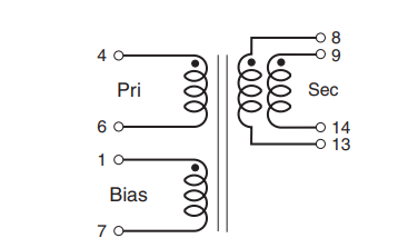
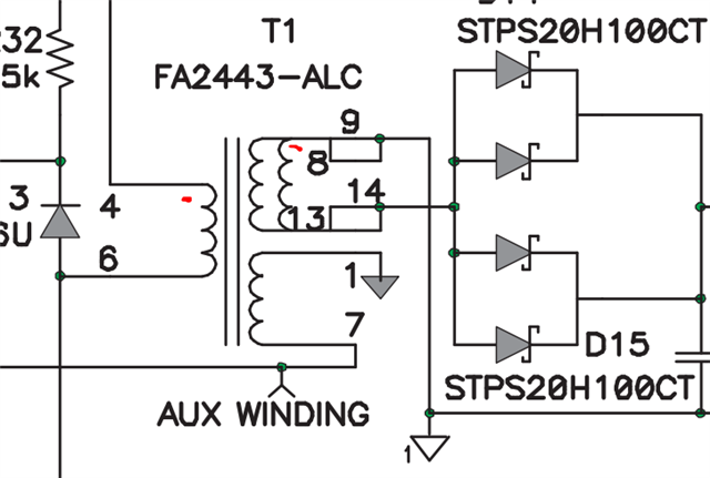
I am designing an AC/DC based on UCC28600, I am uncertain about the input connection of the transformer, that is, Postive and Negative -switching terminal (FA2443-AL - www.mouser.co.uk/.../fa2443-463421.pdf) used in the EVM SMPS (www.ti.com/.../sluu256a.pdf
The FA2443-AL used in the UCC28600 shows that the positive supply is connected to Pin 4 and the Negative (the switching low side) connected to Pin 6 which is the same direction polarity to the secondary side of the transformer. I thought that in a SMPS, the direction polarity needs to be reversed. That is, pin 6 Positive and pin 4 Negative in relation to the secondary seide. If the the connection of the FA2443-AL pins is correct in the UCC28600 EVM, how can you connect a transformer with a different topology (750314782) as the one shown here (https://www.we-online.com/components/products/datasheet/750314782.pdf) Note: ignore the input and output voltage just focus on the topology.
Kind regards,
Bright
Hi Bright,
Thank you for the query on UCC28600.
Pin 4 is the dot and is connected to positive bus. Pin 6 is connected to switched node. Pin 8,9 is the dot and it is connected to ground and pin 13, 14 is connected to diode. So the UCC28600 EVM looks fine and you can follow the same convention.
For 750314782, connect pin 3 to positive of DC input, pin 5 to switch node, pin 6, 7 connect to diode end and 9,10 to sec gnd.
Please let us know if you have any questions.
Regrads,
Harish
Thank you Harish for the clarity
One more question. Please what is the best way of tying together power ground and signal for UCC28600?
Hi Bright,
The best way to isolate power path from the control ground would be to have a star connection at the bulk capacitor. So the power return path from the MOSFET source through the sense resistor will terminate in a short path to bulk capacitor negative. From the bulk capacitor negative take a separate ground for control signal and IC in this way high frequency signals can be decoupled from the controllr ground.
I recommend the following document with some good layout guidelines which should apply to any flyback topology irrespective of controller. (Page 41-50)
The layout example on page 35 of UCC28600 also provides a similar guideline.
There are a lot of reference design in the following link. You can feel free to download altium files from there for reference.
https://www.ti.com/reference-designs/index.html#search?keyword=UCC28600
Regards,
Harish