Hi,
I am using BQ24725A BMS ic for industrial purpose but it is getting 3.3 volt at battery terminal and not getting charge the Battery due to under voltage
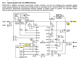
I have same design use as per data sheet.
Please help me.
Thanks,
Original question:

Hi,
I am using BQ24725A BMS ic for industrial purpose but it is getting 3.3 volt at battery terminal and not getting charge the Battery due to under voltage
I have same design use as per data sheet.
Please help me.
Thanks,